CNC Turning and Keyway Machining of Couplings

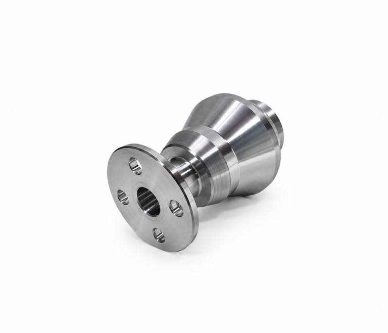
Coupling CNC machining produces components that connect rotating shafts and transmit torque between mechanical assemblies. A typical coupling combines cylindrical surfaces, a central bore, shaft-locating features and one or more keyways.
Turning establishes the rotational geometry, while the keyway operation creates the positive drive interface. Both stages must use a consistent reference so the keyway is correctly positioned relative to the bore.
Establish the Rotational Axis
The workpiece is held in a CNC lathe to machine the front face, outer diameter and central bore. These features establish the main rotational axis of the coupling.
Internal shoulders, retaining-ring grooves and external steps can also be produced during this setup. If the coupling contains two different bore diameters, each section is bored in sequence while the part remains aligned with the spindle.
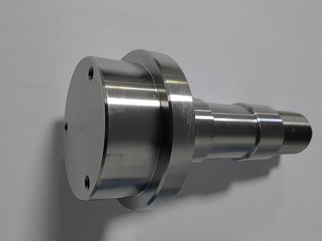
The bore is normally completed before the keyway because it provides the reference surface for later positioning and cutting.
The Keyway Changes the Process
Unlike the turned features, a keyway is not rotationally symmetrical. It requires a separate cutting direction and controlled angular position.
The machining method depends on whether the keyway is internal or external:
| Keyway type | Typical machining method |
|---|---|
| External keyway | End milling or side milling |
| Internal through keyway | Broaching or slotting |
| Internal blind keyway | CNC slotting or specialized keyway cutting |
| Keyway on a turn-mill part | Driven-tool milling |
An external keyway can often be completed on a machining center or turn-mill machine. Internal keyways require sufficient tool access through the bore.
Positioning After Turning
When the part is transferred from a lathe to another machine, the finished bore or outer diameter is used for locating. Soft jaws, an expanding mandrel or a dedicated fixture can hold the coupling while preserving its rotational reference.
On a turn-mill center, the C-axis indexes the spindle to the programmed angular position. A driven tool then cuts the keyway without manually transferring the part to another machine.
This approach is useful when the coupling also contains radial holes, flange holes or milled flats.
Cutting the Keyway
The keyway is normally produced through several passes rather than cutting its full depth at once. Progressive depth reduces tool load and improves chip evacuation.
For internal slotting, the cutting tool makes repeated linear strokes along the bore. Blind keyways require additional clearance planning because the tool cannot pass completely through the component.
Sharp internal corners may require a slotting or broaching process because a rotating end mill leaves a corner radius.
Completing the Coupling
After machining, the keyway edges, bore entrance and shaft-facing surfaces are deburred. The bore, keyway and locating features are checked against the customer’s drawing before delivery.
Reliable coupling CNC machining depends on establishing the bore accurately, selecting the correct keyway process and maintaining a consistent reference between the turned and slotted features.