Turn-Mill Machining of Optical Adjustment Mounts
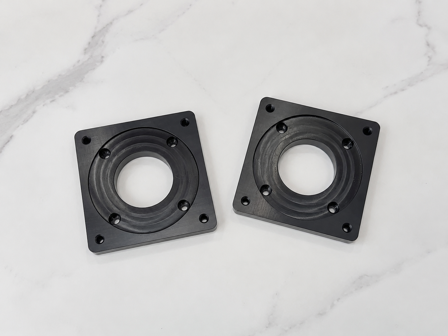
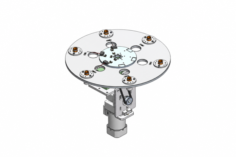
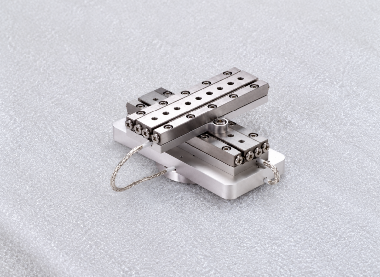
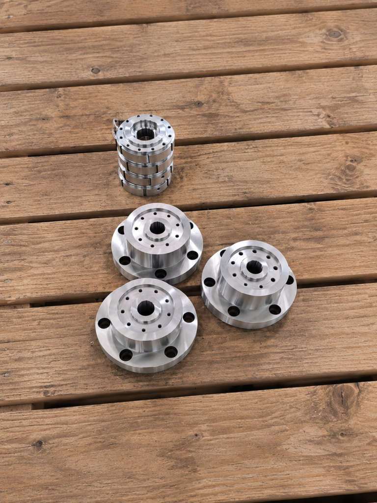
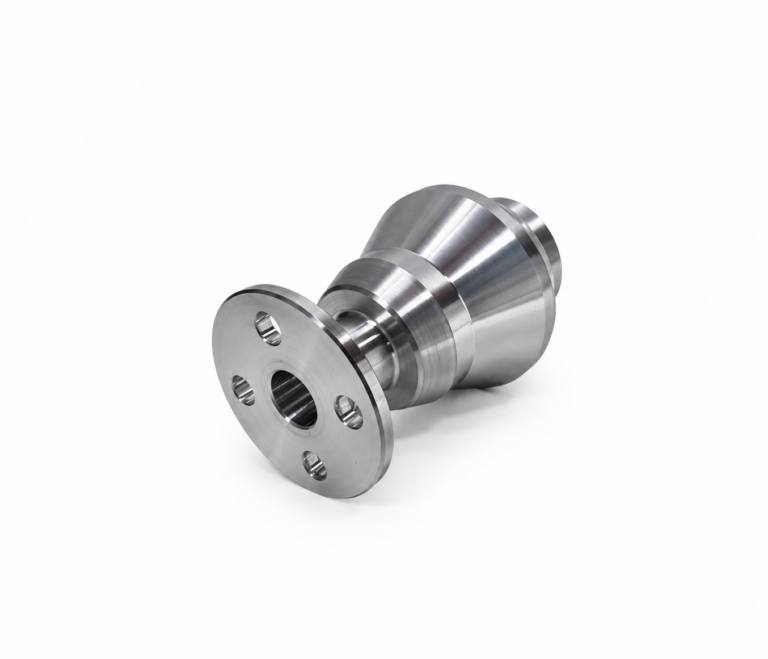
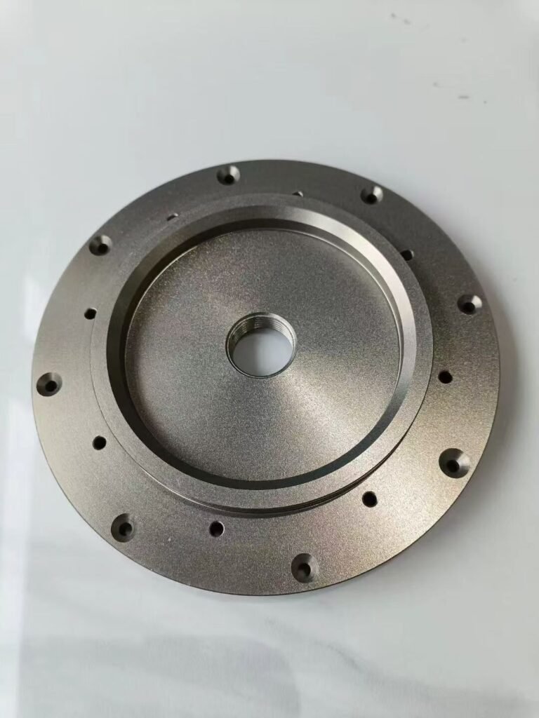
Optical rotation mount machining produces mechanical components used to hold and rotate optical elements within an equipment assembly. A typical mount may combine a circular body, central locating bore, adjustment slots and side locking features.
Because these features depend on the same rotational center, turn-mill machining provides an efficient way to complete them from a common setup.
Starting with the Rotational Features
The component is first held in the main spindle so its circular geometry can be established. CNC turning produces the outer diameter, front face, central bore and concentric locating steps.
Machining these features without releasing the workpiece preserves their relationship to the spindle axis. Grooves for retaining rings or internal shoulders for mounting inserts can also be completed during this stage.
Enough stock may be retained on thin sections until the main turning operations are finished. This provides additional support and limits vibration during internal boring.
Transitioning from Turning to Milling
After the rotational features are established, the spindle indexes the component to specific angular positions. Driven tools can then produce the non-circular features without transferring the part to a separate machining center.
Radial holes, locking-screw threads and adjustment slots are machined relative to the original spindle center. A C-axis controls angular position, while a Y-axis may be used for features that do not pass through the component centerline.
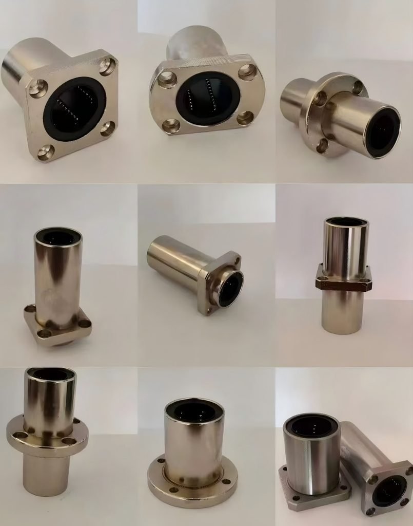
This combined process reduces the number of fixtures and limits alignment differences between turned and milled features.
Machining the Adjustment Mechanism
An optical rotation mount may contain an arc-shaped slot that defines its adjustment range. The slot can be milled through a coordinated movement of the linear and rotary axes.
Side holes for locking screws require a stable entry surface. When the drill approaches a curved outer diameter, a small spot face may be machined first to prevent the tool from sliding.
Fine internal threads can be produced by tapping or thread milling. Thread milling is useful for blind holes where controlled depth and chip removal are important.
Managing Thin Circular Sections
Removing material for slots and side openings reduces the rigidity of the circular body. The machining sequence should therefore complete the main bore and locating surfaces before large openings weaken the structure.
Cutting forces should remain balanced around the component. Light finishing passes help prevent local movement when machining narrow rings or thin retaining sections.
Completing the Mount Component
After machining, slot edges, threaded holes and bore entrances require controlled deburring. The central bore, locating steps and adjustment features are checked against the customer’s drawing before delivery.
Reliable optical rotation mount machining depends on establishing the rotational geometry first and completing indexed features from the same reference. Turn-mill equipment supports this relationship while reducing handling between separate machining operations.