Assembling Aluminum at Different Temperatures
The Part Passed Inspection at 20°C
Aluminum thermal expansion can create an assembly difference even when every inspection result is acceptable.
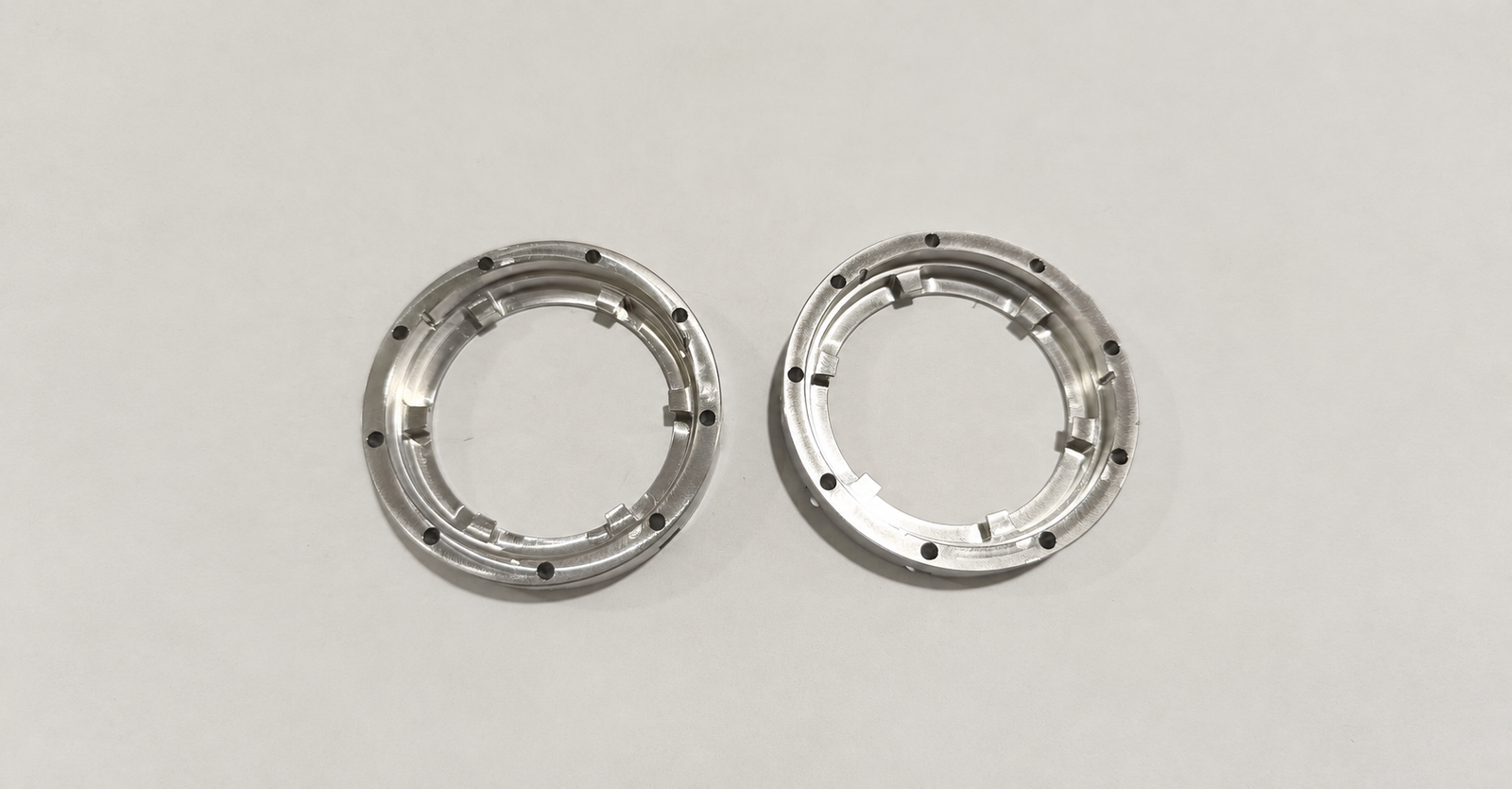
A machined aluminum housing was measured in a controlled inspection room at 20°C. The bore diameter, mounting-hole pattern, and sealing face all passed. Later, the housing was assembled in a 35°C production area. The mating component became difficult to locate, and a clearance that looked sufficient during inspection had nearly disappeared.
Nothing had changed in the drawing. The temperature had.
Aluminum expands as its temperature rises. For a 15°C increase, the dimensional change can be significant when tolerances are tight, features are large, or the mating component uses a different material.
Calculate the Expected Size Change
A simplified calculation is:
ΔL = α × L × ΔT
Where:
ΔLis the dimensional changeαis the linear thermal-expansion coefficientLis the original dimensionΔTis the temperature change
For aluminum near room temperature, a typical coefficient is approximately 23 × 10⁻⁶/°C.
With a 15°C increase from 20°C to 35°C:
- A 100 mm aluminum length grows by approximately 0.035 mm.
- A 300 mm aluminum length grows by approximately 0.104 mm.
- A 50 mm aluminum bore increases in diameter by approximately 0.017 mm.
These values may be small for general fabrication, but they can exceed the usable clearance in precision locating features, press fits, bearing seats, seal grooves, and close-tolerance hole patterns.
A Bore Does Not Behave Like a Fixed Dimension
When the temperature rises, an aluminum bore becomes larger—not smaller. An aluminum shaft also becomes larger.
If both mating parts are made from the same aluminum alloy and reach the same uniform temperature, their relative fit may change only slightly. But real assemblies are often mixed-material systems.
For example, an aluminum housing and steel shaft will not expand at the same rate. The aluminum bore generally grows more than the steel shaft as temperature increases, increasing clearance. The reverse concern can occur when an aluminum shaft runs inside a steel or cast-iron feature.
Temperature gradients create another risk. A housing heated by nearby equipment may expand before the internal steel component reaches the same temperature. Temporary misalignment, uneven preload, or altered sealing load can result.
Inspection and Assembly Must Use the Same Reference
A drawing dimension is normally interpreted at a stated reference temperature, commonly 20°C. If inspection occurs near that condition but assembly occurs at 35°C, the dimensional condition is not identical.
For critical features, the production plan should define:
- The inspection reference temperature.
- The expected assembly-temperature range.
- The materials of mating components.
- Which fits, locations, and sealing features are temperature-sensitive.
- Whether thermal compensation is required during measurement.
Do not assume that an in-tolerance inspection result at 20°C guarantees the same functional fit at 35°C.
Design for the Actual Operating Condition
The correct solution is not always to machine the aluminum part smaller or larger. First identify the functional temperature and calculate the complete tolerance stack across all mating materials.
For high-precision assemblies, stabilize components before measurement and assembly. Avoid comparing a cool aluminum housing with a warm steel shaft. Where the operating temperature is known, use it during tolerance analysis and define any compensation strategy on the drawing or process specification.
Conclusion
A 20°C aluminum part will grow at 35°C. Over a 15°C change, the effect can reach several hundredths of a millimeter on common CNC dimensions.
When fits are tight, temperature is part of the dimension—not just part of the environment.