Concentricity vs. Circular and Total Runout
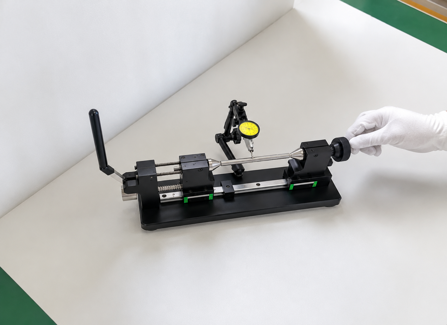
Three Symbols, One Shaft
Runout tolerance is often specified when a CNC drawing requires a rotating feature to stay aligned with a datum axis.
During a drawing review for a stepped shaft, the team considered three possible controls for one critical diameter: concentricity, circular runout, and total runout.
The first question should not be which tolerance is tighter. It should be: what must the feature do in the assembled product?
This article uses common ASME GD&T terminology. Always confirm the governing drawing standard before releasing a specification.
Use Circular Runout for One Functional Cross-Section
Circular runout controls the indicator variation at one circular cross-section while the part rotates around its datum axis.
It is useful when a rotating diameter, shoulder, or face must run smoothly relative to a reference axis at a specific location. For example, a short bearing seat or a pulley location may need circular runout control to limit visible wobble during rotation.
However, circular runout is checked one section at a time. A long shaft can pass circular runout at individual locations while still having variation along its full length.
Specify circular runout when the functional concern is local radial variation—not the complete surface condition.
Use Total Runout for the Entire Surface
Total runout evaluates the surface while the part rotates and the indicator travels across the full controlled length.
This makes total runout more comprehensive for a cylindrical surface. It controls the relationship to the datum axis while also limiting accumulated surface variation, including effects from taper, straightness, roundness, and coaxiality.
For a long sealing journal, precision bearing seat, or rotating shaft diameter that must remain stable over its entire length, total runout is often the more functional callout.
It is also more demanding to manufacture and inspect. Do not apply total runout simply because the part “looks precision.” Use it when the entire rotating surface affects fit, sealing, or motion.
Use Concentricity Only for Its Specific Purpose
Concentricity controls derived median points of a feature relative to a datum axis. It is not a direct control of the physical surface that a dial indicator touches.
Because inspection can be complex and the result may not reflect actual rotational surface error, concentricity is uncommon in many modern drawings. In most cases, position, circular runout, or total runout communicates functional intent more clearly.
Concentricity may still be appropriate when the design truly requires control of the feature’s median-point distribution, rather than its surface behavior during rotation. That is a specialized requirement and should be selected deliberately.
A Practical Selection Rule
Use this decision path during drawing review:
1.Does one circular section need controlled rotation?
Use circular runout.
2.Does the full length of a rotating surface need to stay stable?
Use total runout.
3.Is the concern specifically the derived median points, rather than the surface?
Consider concentricity, but confirm that the inspection method supports it.
The datum is equally important. Establish the datum axis from the feature that actually locates the part in assembly, such as a bearing journal, precision bore, or center feature.
Conclusion
A runout tolerance should describe functional behavior, not serve as a generic substitute for “make it concentric.”
Circular runout controls a local section. Total runout controls the complete rotating surface. Concentricity addresses a more specialized median-point requirement.
Choosing the right control makes the part easier to quote, machine, inspect, and assemble correctly.