CNC machining 0.0005 inch flatness
Machining Structural Components for Optical Instruments:
Machining Structural Components for Optical Instruments:
Why Are Flatness and Perpendicularity Requirements Ten Times Stricter Than for Standard Mechanical Parts?
It is not the entire component that requires such strict tolerances, but rather the optical reference surfaces.
In the machining of structural components for optical instruments, flatness and perpendicularity requirements are often an order of magnitude stricter than those for standard mechanical parts. While a mounting surface on a standard equipment bracket might only need to meet a tolerance of 0.05 mm to 0.10 mm for assembly, critical optical reference surfaces—such as those for lens mounts, detector mounts, aperture mounts, and collimator brackets—often require tolerances in the 0.005 mm to 0.01 mm range.
This is not because the optical industry prefers complex engineering drawings, but because even minute errors in the orientation of structural components are amplified by the optical path. Slight warping of a mounting surface can lead to lens tilt, focal plane drift, or non-coplanarity of sensor surfaces, requiring significant time for compensation during subsequent alignment and adjustment.
Why Do Optical Structural Components Magnify Orientation Errors?
For standard mechanical parts, poor flatness typically results in assembly gaps, localized stress concentrations, or visible seam irregularities. Optical structural components are different; their mounting surfaces usually dictate the spatial orientation of lenses, prisms, detectors, or apertures. A tiny angular error, when amplified over the distance of the optical path, can translate into image displacement or calibration instability.
The same applies to perpendicularity. If a bracket’s sidewall is not perpendicular to its base, the sensor may appear securely mounted, yet its sensitive surface will actually be misaligned from the design angle. Relying on shims, adhesives, or alignment adjustments to correct this later is both time-consuming and detrimental to batch consistency.
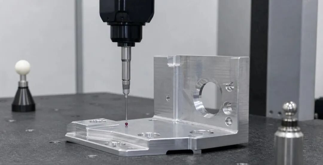
Therefore, evaluating these parts based solely on external dimensions is insufficient. It is crucial to assess critical planes, locating holes, end faces, and optical reference surfaces within a unified inspection coordinate system.
Machining Stage: Controlling Clamping and Stress
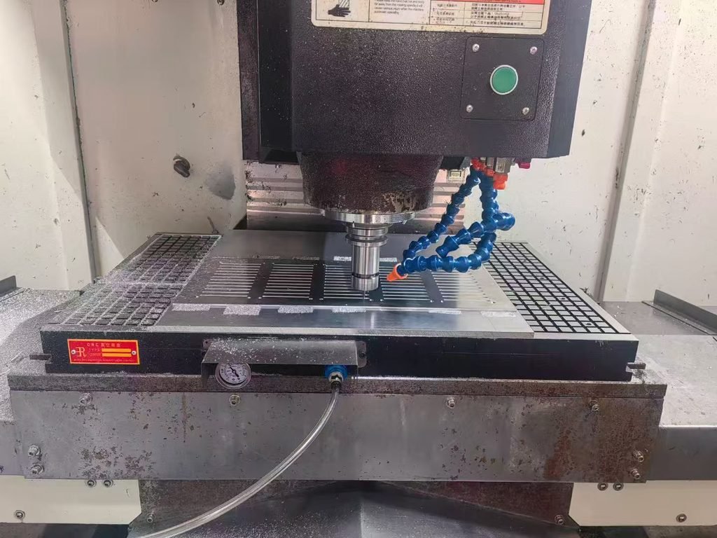
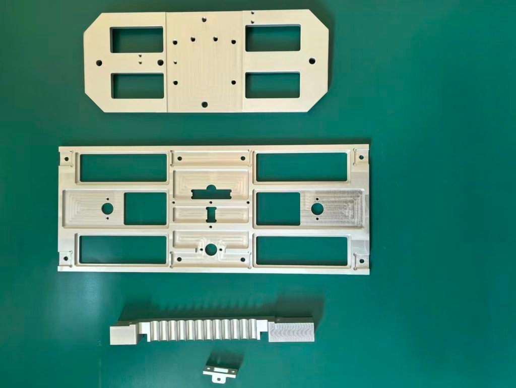
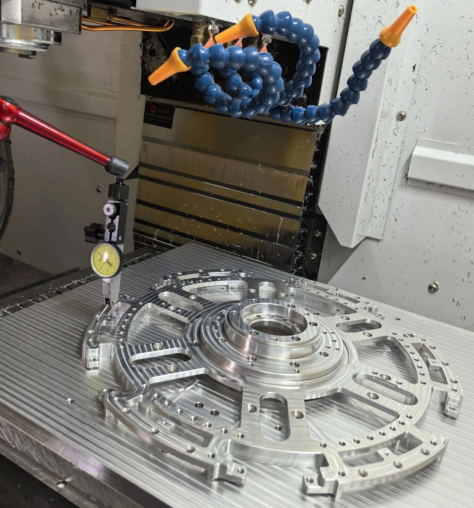
Structural components for optical instruments are commonly made from Al6061, Al7075, stainless steel, and PEEK. Aluminum alloys are ideal for lightweight designs and anodized finishes, but extensive pocketing, thin walls, and single-sided material removal can induce deformation. Stainless steel offers high rigidity but is more prone to issues with tool wear and burrs. With PEEK, clamping pressure and thermal spring-back must be carefully controlled. In terms of manufacturing processes, critical surfaces typically require rough and finish machining stages, symmetrical material removal, low-stress clamping, and finish re-milling. 5-axis simultaneous machining can be used for complex structures to minimize part flipping, while vacuum chucks, soft jaws, or sacrificial ribs can be considered for thin plates or large flat surfaces. The goal is not to showcase equipment capabilities, but to minimize datum drift between process steps.
If the part requires black anodizing, sandblasting, or black oxide treatment, decisions must be made in advance regarding masking mating datums and locating holes, accounting for coating thickness, and conducting post-treatment inspections.
Common Pitfalls
The first pitfall is applying a tight tolerance (e.g., 0.005 mm) to the entire part. This drives up costs without necessarily improving optical performance.
The second pitfall is specifying flatness without defining the inspection datum. Without a datum, measurement results are open to conflicting interpretations.
The third pitfall is assuming the job is done once the part passes inspection immediately after machining. Processes such as black anodizing, sandblasting, or cleaning and packaging can still affect critical mating surfaces and, consequently, final assembly and alignment.
Why do optical structural components have stricter flatness requirements?
Flatness affects the spatial orientation of lenses, detectors, or apertures; minute errors can be magnified by the optical path, leading to focal plane drift or assembly instability.
Do all surfaces of optical structural components require 0.005 mm flatness?
No. Strict control is only necessary for optical datums, mating surfaces, and critical mounting surfaces; tolerances for general clearance surfaces should not be tightened unnecessarily.
What should be considered when inspecting perpendicularity?
The reference datum (surface or hole) for the perpendicularity evaluation must be specified; ideally, the inspection coordinate system should be established based on the assembly datum.
Is re-inspection required after anodizing?
Re-inspection is recommended for critical holes, mating surfaces, and optical datums after processing, as coating thickness, sandblasting, and cleaning can alter the final state of the part.