high precision CNC milling concentricity 0.0001 inch
Guide to High-Precision CNC Machining for Optical Mounts: Achieving 0.0001-Inch Coaxiality and Flatness
The core of an optical system lies in the positioning accuracy of the mirror mounts and brackets. If the flatness of an optical mount falls outside tolerance limits, it directly causes lens tilting and optical axis misalignment, necessitating repeated adjustments to the entire optical path. Through a combination of 5-axis single-setup machining, constant-temperature control, and stress-relief processes, flatness can be stabilized within 0.0003 inches and coaxiality controlled within 0.0001 inches.
CNC Precision Requirements for Optical Mounts: From Optical Design to Machining Control Points
Machining requirements for optical mounts essentially translate the optical design’s specifications regarding lens position and angle into concrete tolerances and process parameters executable by CNC machines. Simply put, flatness control ensures the flatness of the mounting reference surface, while coaxiality control ensures the alignment of the centerlines of the lens barrel bores; together, they determine whether the optical path can align within the design’s error margins.
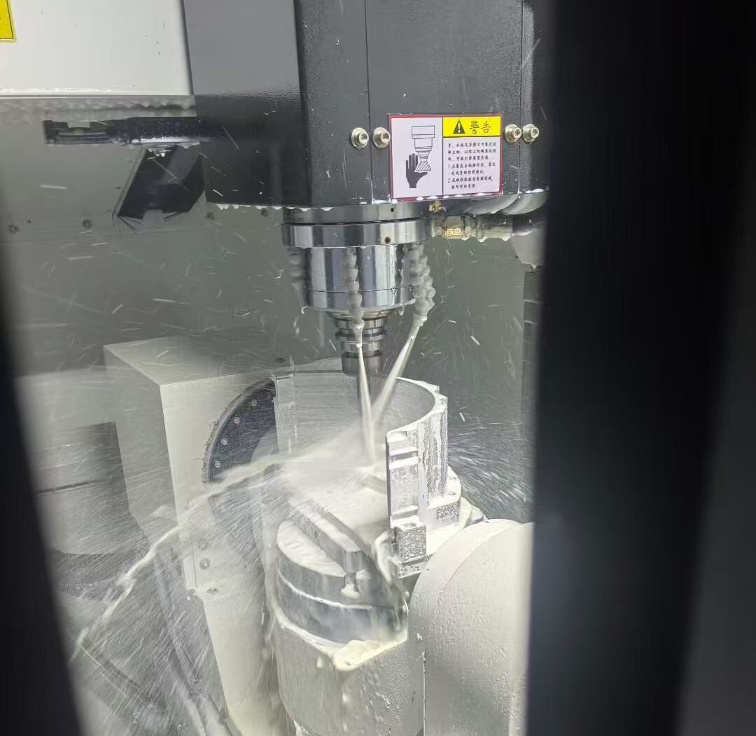
Three Machining Stages Prone to Issues:
Rough Milling Stage
: High material removal rates and insufficient internal stress relief lead to slow deformation after the part is removed from the machine. In practice, mounts that undergo finish milling immediately after rough milling often experience a flatness “rebound” of 0.0003–0.0005 inches after sitting for 12 hours.
Finish Milling Stage
: Accumulation of cutting heat causes thermal expansion, followed by dimensional contraction upon cooling. A constant-temperature workshop (20±1°C) combined with ample coolant application can keep this error within 0.0001 inches.
Inspection Stage
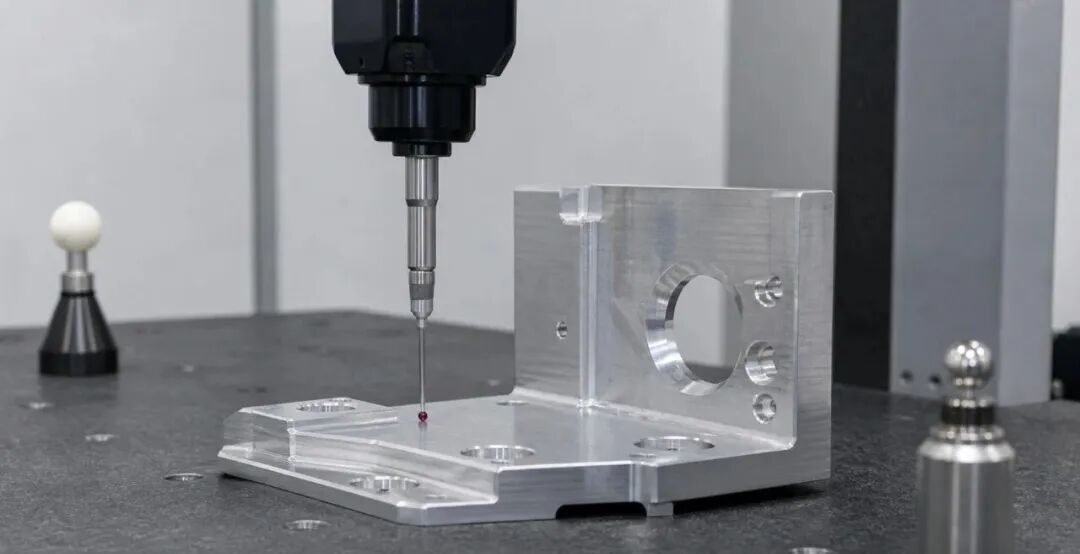
: Measurements are valid only when taken from the same reference. If the inspection datum differs from the assembly datum, the component will fail to align during assembly, regardless of how impressive the CMM (Coordinate Measuring Machine) data appears.
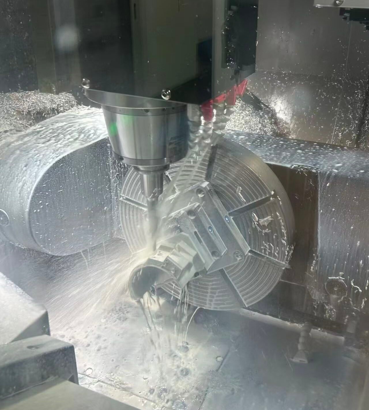
Process Route Design: Ensuring CNC Precision via 5-Axis Single-Setup Machining
From receiving the blueprints to mass delivery, the process route directly determines the upper limit of the finished product’s precision. Our solution comprises four core stages.
Workholding Strategy Selection
Optical mounts often feature thin walls and low rigidity; deformation caused by clamping is a major factor compromising precision.
Vacuum Chucking
: Suitable for large, flat, thin-walled brackets; provides uniform suction force and maintains flatness within 0.0005 inches over a 180mm × 120mm area.
Mandrel Positioning
: Suitable for lens barrel-type components; the part is secured between centers on a mandrel, allowing for indexed rotation to machine various hole locations while maintaining concentricity within 0.0002 inches.
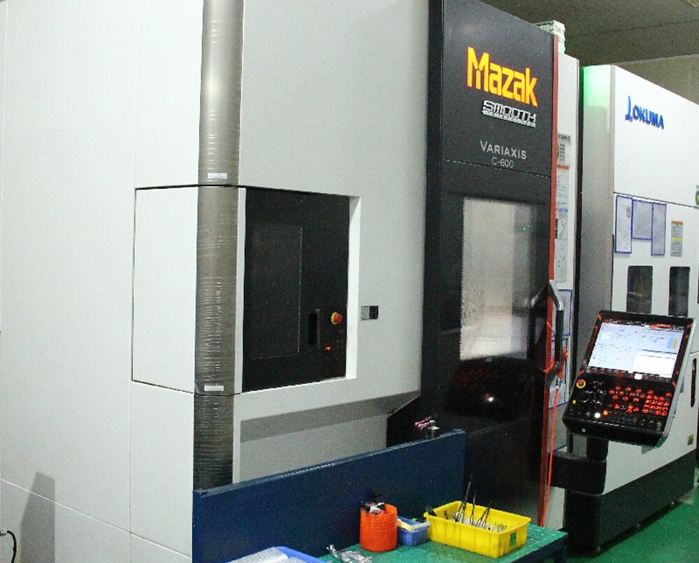
5-Axis Single-Setup Machining
: Suitable for complex, multi-faceted brackets; multiple datum surfaces and hole locations are machined in a single setup, eliminating datum shift errors caused by re-clamping.
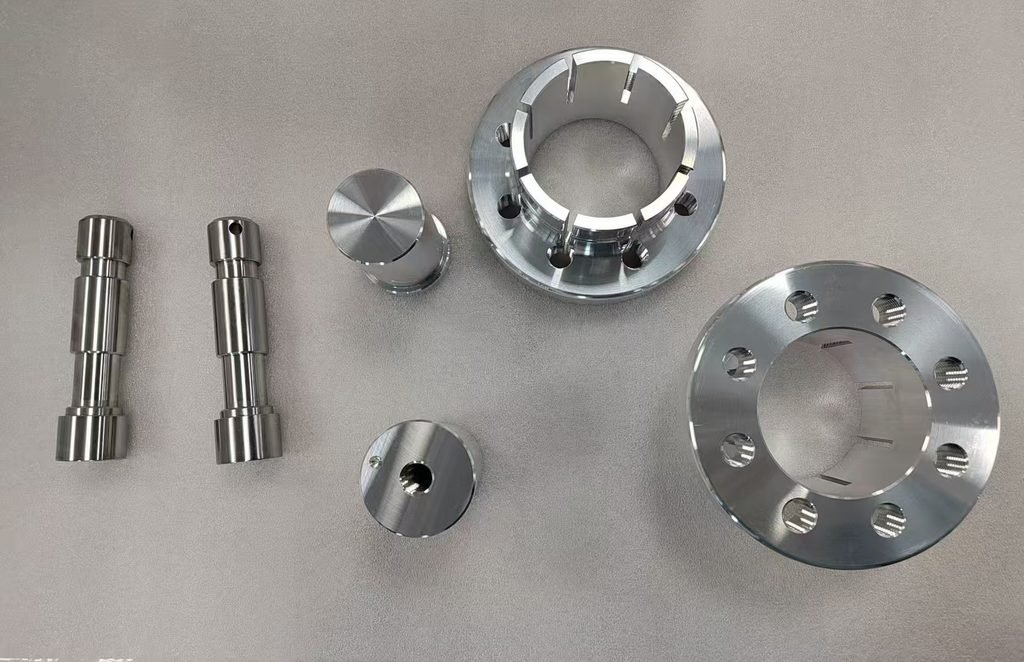
Common Misconceptions
Misconception 1: High precision alone guarantees successful assembly
Flatness and concentricity data only confirm the quality of the individual part; the alignment of assembly datums is equally critical. It is recommended to request a DFM (Design for Manufacturability) analysis from the machine shop during the design phase to ensure inspection datums and assembly datums are consistent.
Misconception 2: A passing first article guarantees batch quality
Issues such as stress-induced deformation, tool wear, and thermal expansion often only emerge during batch production. The key lies in process monitoring via SPC (Statistical Process Control)—such as spot-checking every 10 parts—and making adjustments if the Cpk drops below 1.2.
Misconception 3: Uniform wall thickness minimizes deformation
In reality, the opposite is often true; while uniform wall thickness results in consistent thermal and force distribution during machining, deformation becomes more unpredictable after stress is released. Strategically adding stiffening ribs or using variable wall thicknesses can actually help control the direction of deformation.
Misconception 4: Equipment precision alone ensures concentricity
While equipment precision is the foundation, achieving concentricity in batch production relies heavily on process planning: unified datums, single-setup machining, and in-process compensation are all essential. Relying solely on 5-axis equipment without optimizing programming and toolpaths will still fail to achieve 0.0001-inch precision.