CNC Milling Supplier for Industrial Machinery Parts Serving Boston
Three Typical Part Machining Strategies and Five Key Selection Principles for CNC Milling
I. Three Typical Part Machining Strategies
Strategy 1: Square Plate Parts (AISI 1045 / 45 Steel)
A typical entry-level part; the blank is a 100×80×27mm rectangular block. With the bottom surface pre-machined, the top surface, profile, holes, and slots require machining. The process utilizes the bottom surface as the precision datum, completing all operations in a single setup to ensure hole circular runout and perpendicularity. Roughing parameters are 800 rpm spindle speed and 60 mm/min feed rate; finishing parameters are 1000 rpm and 80 mm/min, with a 0.2mm finishing allowance. This is a standard exercise for beginners.
Strategy 2: Flat Grooved Cam (HT200 Cast Iron)
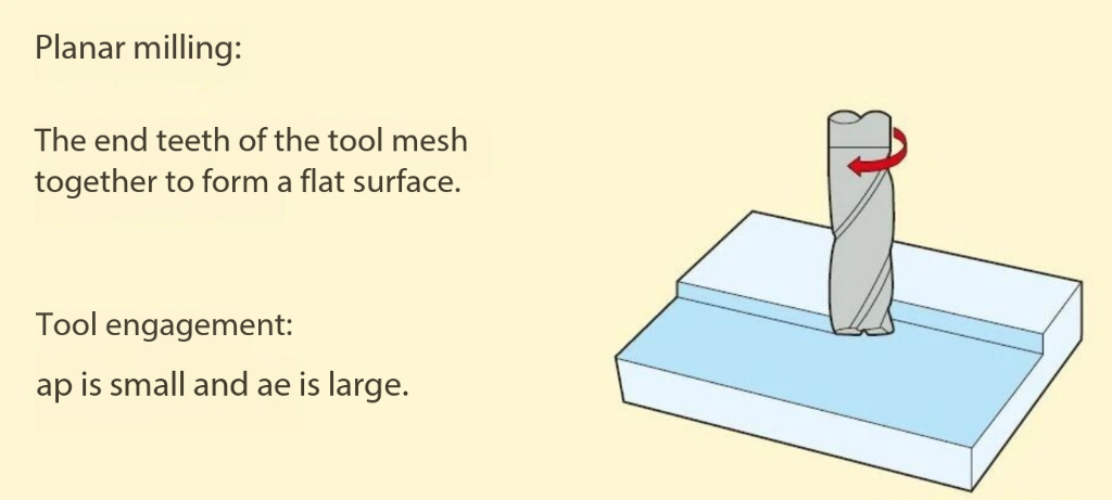
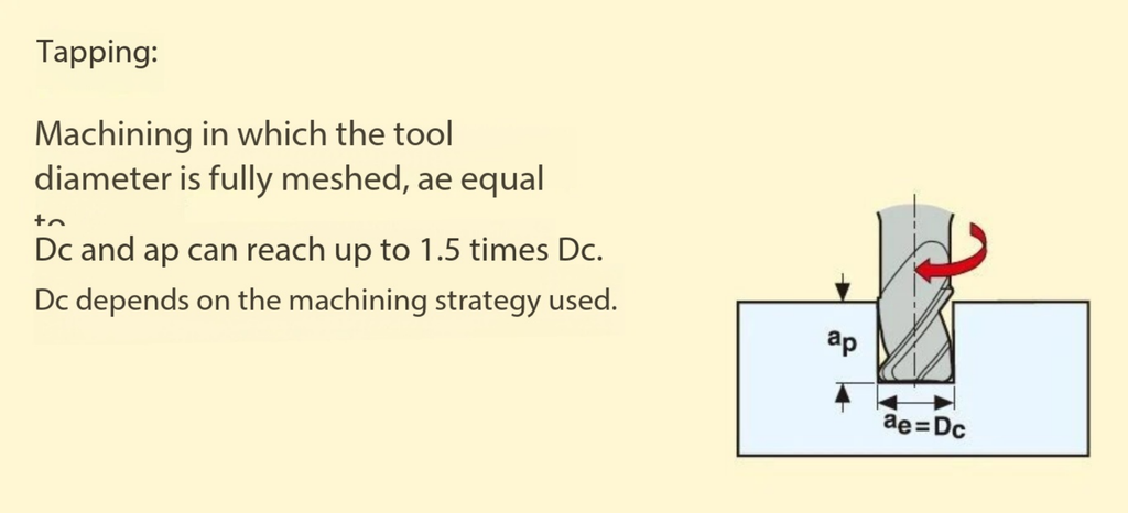
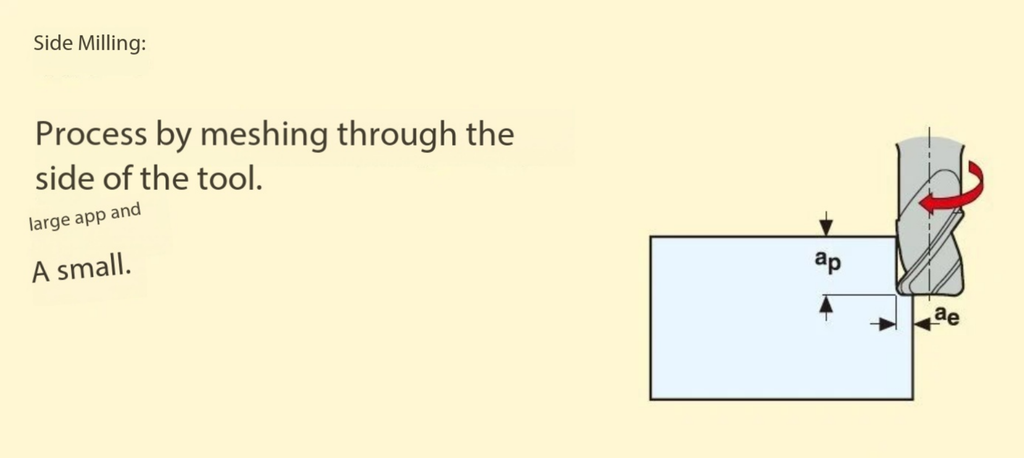
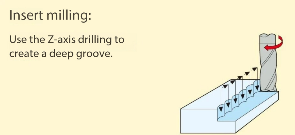
A classic part for two-axis simultaneous milling, where profile accuracy and slot wall quality are critical. Positioning utilizes the “one-face, two-hole” method. Tangential entry is used for the outer profile, while the inner profile is entered via a transition arc to avoid tool marks. Depth increments are achieved through reciprocating milling (gradual plunging), eliminating the need for extra process holes. An 18mm carbide end mill is selected; climb milling is used throughout, with roughing and finishing operations separated. Perpendicularity is ensured by aligning the fixture plane during setup, resulting in high product stability.
Strategy 3: Irregular Shift Lever Part (HT200 Cast Iron – Medium-Batch Production)
This irregular part features a distributed structure; while conventional machine tools would require over a dozen operations, a machining center allows for process consolidation, completing the job in just three steps. The outer cylindrical blank surface serves as the rough datum to ensure uniform machining allowance, while the “one-face, two-hole” method acts as the unified precision datum. Milling, slotting, and drilling/reaming are consolidated into a single operation, with a milling step interspersed between drilling stages to dissipate heat and minimize deformation; this approach more than doubles efficiency in medium-batch production.
II. Five Key Principles for Selection
1. Principles for Verifying Part Drawings and Structural Manufacturability
Upon receiving the drawings, the first step is not to consider machining methods but to review the drawings themselves: check if the views are complete and clear, if dimensions and tolerances are fully and reasonably specified, and if technical requirements are explicit. Next, assess structural manufacturability—looking for issues such as drilling on inclined surfaces, deep slots lacking tool retraction space, or inconsistent slot widths. Communicate early regarding potential structural optimizations; often, a minor change like adjusting a chamfer or standardizing a slot width can cut machining time in half. Finally, verify material properties to lay the groundwork for subsequent tool selection and parameter setting.

2. Principles for Selecting and Prioritizing Datums
An incorrect datum choice renders subsequent efforts futile. For rough datums, prioritize ensuring uniform machining allowance on critical surfaces while accounting for the positional requirements of non-machined surfaces; use a datum only once in any given dimensional direction to prevent error accumulation. For finish datums, prioritize the principle of datum coincidence—aligning with the design datum whenever possible to eliminate errors caused by misalignment. In mass production, prioritize a unified datum strategy (such as the classic “one-face, two-hole” positioning method) where multiple operations share the same datum; this saves setup time and ensures stable positional accuracy.

3. Principles for Matching Operation Sequencing
Decisions on whether to concentrate or disperse operations should align with production volume and part characteristics. For single-piece or small-batch production, concentrate operations—having a single machine tool perform as much processing as possible to minimize part handling. For large-batch or mass production, disperse operations to facilitate assembly-line workflows. For heavy parts, concentrate operations to reduce the labor involved in loading and unloading; for high-precision parts with low rigidity, disperse operations to allow for stress relief. Regarding machining sequence, remember the rule: “roughing before finishing, surfaces before holes, and datums first”; following this prevents fundamental errors in approach.
4. Principles for Prioritizing Cutting Parameters
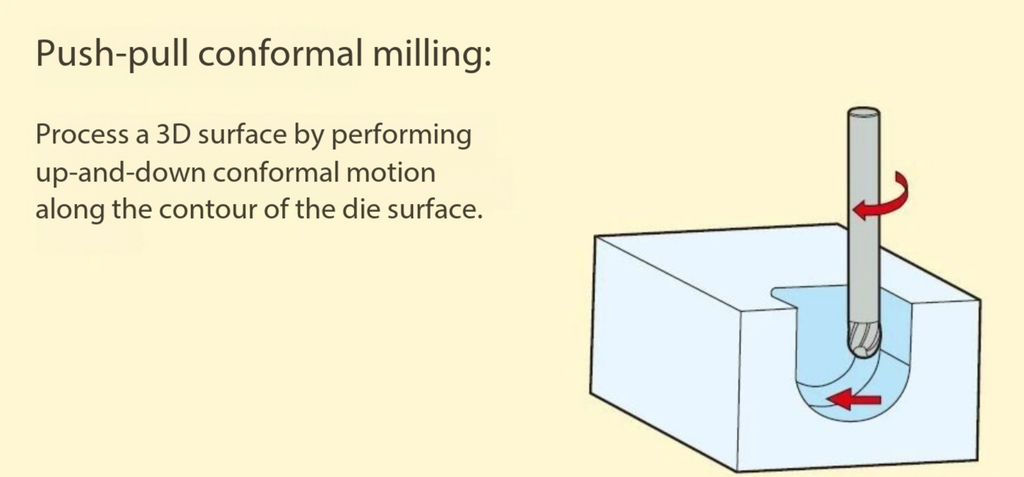
Many novices determine spindle speed first when selecting parameters, but this reverses the correct order. The proper priority is: first determine the depth of cut, then select the feed rate, and finally calculate the cutting speed. For roughing, aim to remove the entire machining allowance in a single pass to maximize efficiency; for finishing, leave an allowance of approximately 0.2 mm for the final milling pass, prioritizing surface quality. Practical application also requires attention to detail: reducing the feed rate at contour corners to prevent over-cutting, and adjusting parameters for ductile materials to ensure effective chip breaking—these are examples of hands-on expertise not typically found on engineering drawings.
5. Principles of Workholding and Tool Selection
The core considerations for workholding are rigidity and alignment accuracy. This is particularly critical for parts with stringent positional requirements, such as cams and irregularly shaped components, where the flatness of the fixture and the precision of locating pins directly determine the quality ceiling of the finished product. Cutting tools must be matched to the part’s geometry and material; for instance, the diameter of a slot-milling cutter must correspond to the slot width, while carbide tools offer the best cost-performance ratio for cast iron components.