Controlling Anodized Bore Tolerance to Prevent Assembly Failure
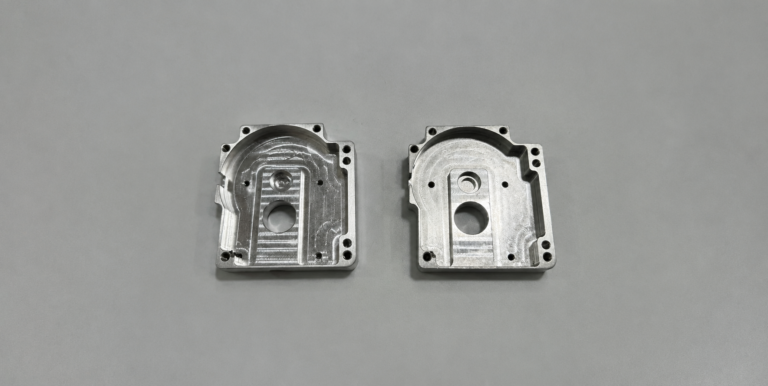
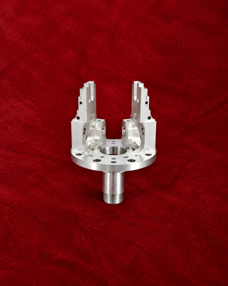
Composite position tolerance was satisfied when the aluminum component completed machining inspection. The bore pattern met its location requirements, and the mating parts assembled correctly before surface treatment.
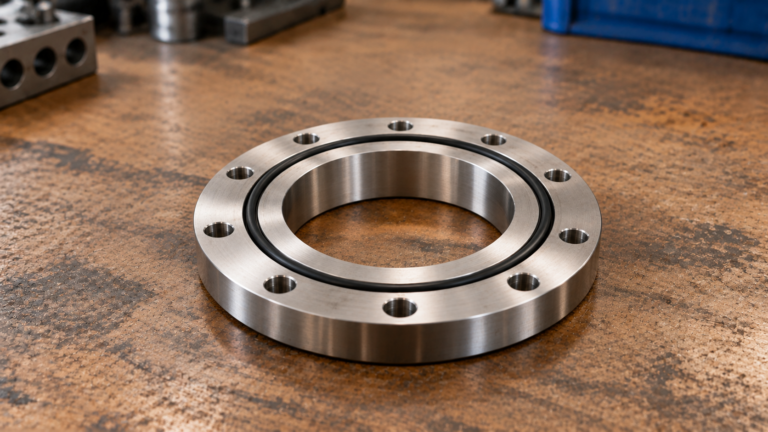
After anodizing, however, the mating shaft could no longer enter one of the precision bores. Although the hole positions remained acceptable, coating buildup had reduced the effective diameter and removed the required assembly clearance.
The failure showed that positional accuracy alone cannot guarantee assembly. Bore size, anodizing allowance, and final fit must also be controlled after surface treatment.
Why the Bore Became Smaller
Anodizing converts the aluminum surface into an oxide layer. Part of the coating penetrates the base material, while part grows above the original surface.
Inside a bore, outward growth occurs around the complete circumference. The finished diameter therefore becomes smaller after treatment.
The dimensional change depends on the anodizing type, specified coating thickness, material condition, and process control. A general allowance cannot be applied safely to every part.
Finding the Source of the Failure
Inspection records confirmed that the bore was correct before anodizing. Measurement after treatment showed that its diameter had moved below the lower tolerance limit.
The original drawing specified the final bore size but did not clarify whether the dimension applied before or after surface treatment. The machinist had therefore produced the nominal finished dimension before anodizing.
This left no room for coating buildup.
Choosing the Correct Control Method
The required solution depended on the function of the bore.
For a bore that needed corrosion protection, the machining diameter was increased by a controlled allowance. Trial parts were anodized and measured to establish the actual dimensional change from the selected supplier and coating specification.
For an extremely tight bearing or locating fit, masking or plugging the bore was considered. This prevented coating buildup on the functional surface, although the uncoated area required approval because its corrosion protection would be different.
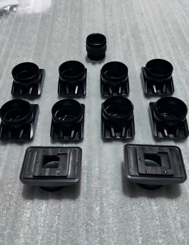
Post-anodizing machining was another option, but it removed the protective coating and could create a visible color boundary. It was used only when the functional requirement justified it.
Measuring the Bore Correctly
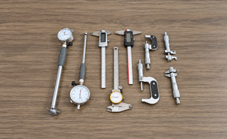
The bore was inspected using a suitable bore gauge rather than relying only on calipers. Measurements were taken at multiple depths and directions to identify taper or uneven coating.
Temperature and cleanliness were controlled before final inspection. Coating residue, sealing deposits, or measurement near the bore entrance could otherwise produce misleading results.
A functional gauge or mating component was also used when assembly performance was the final acceptance condition.
Updating the Drawing and Process
The drawing was revised to identify the bore size as a post-anodizing requirement. The coating type and expected thickness were linked to the dimensional specification.
Machining instructions included the required pre-treatment allowance, while the inspection plan recorded bore dimensions both before and after anodizing.
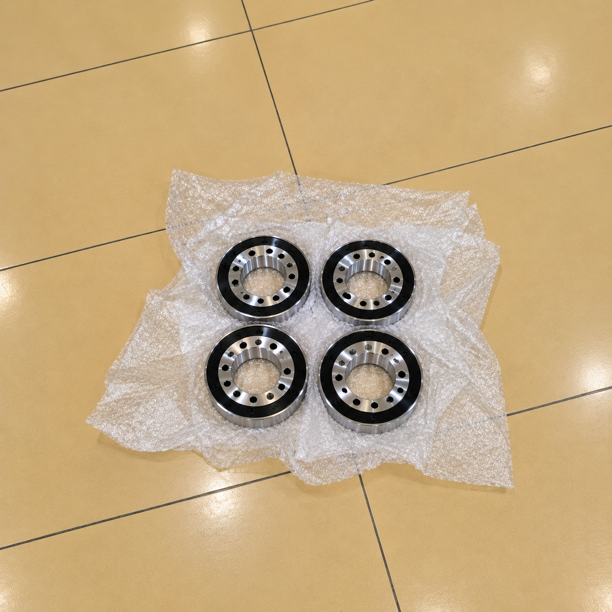
With these controls in place, the treated components assembled correctly without forcing or additional rework.
This case demonstrates that anodized bore tolerance cannot be treated as a finishing detail. Machining allowance, coating specification, masking decisions, and final inspection must be planned as one process.
We manufacture precision anodized aluminum components with controlled bores, threads, and mating features. Send us your drawing, fit requirement, coating specification, and assembly details for a manufacturability review.