Matched-Pair Machining for Robotic Gripper Fingers
Both gripper fingers passed individual dimensional inspection. After assembly, however, one side contacted the workpiece earlier than the other.
The issue was not a single dimension outside tolerance. It was the accumulated difference between two mirrored parts.
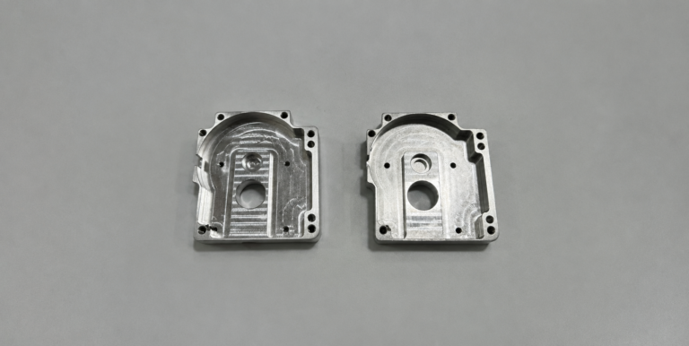
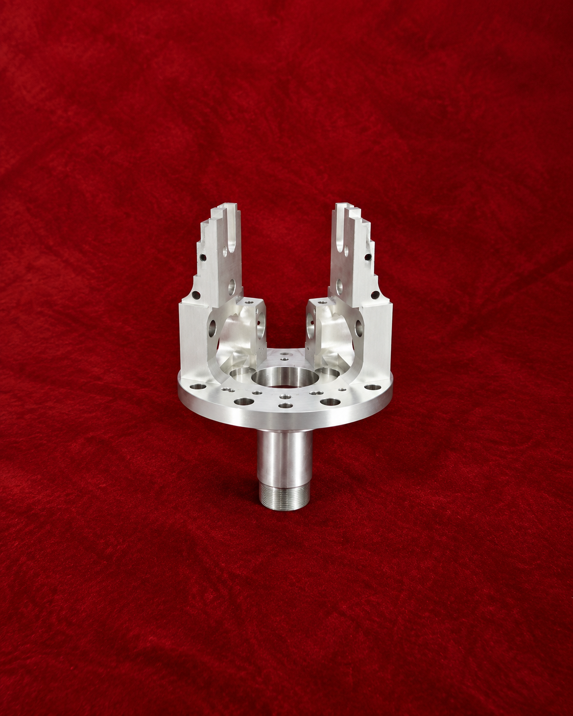
In robot gripper finger machining, the left and right components must function as a pair. Their mounting holes, guide surfaces, gripping faces, and overall height must remain closely matched.
Why Two Acceptable Parts May Not Work Together
A drawing normally defines the tolerance of each component. If one finger is close to the upper tolerance limit and the other is close to the lower limit, both parts can pass inspection while producing an uneven assembly.
Small differences in pivot-hole position, mounting height, or gripping-face location can affect when each finger contacts the workpiece. The gripper may apply force unevenly or shift the component away from its intended center.
Tool wear and separate machining setups can increase these differences, especially when the left and right fingers are produced at different times.
Treating the Fingers as One Functional Set
The manufacturing plan began by identifying the features that controlled gripper movement.
Common datums were established from the mounting interfaces rather than from non-functional exterior surfaces. The mirrored components were programmed from the same coordinate logic and machined under equivalent setup conditions.
Where practical, both fingers were produced from the same material batch and with the same cutting tools. This reduced variation caused by material condition, tool wear, and process changes.
The left and right parts were kept together as a matched set throughout machining, deburring, inspection, and packaging.
Controlling the Critical Relationships
The most important features were not always the most visually complex.
Mounting-hole positions controlled how each finger connected to the gripper body. Guide surfaces affected sliding motion, while the gripping faces determined contact position and force distribution.
These features were finished after the main material-removal operations. Leaving a controlled allowance helped prevent rough-machining stress from changing the final geometry.
The gripping faces were machined using the same tool condition and finishing strategy. This maintained similar height, texture, and edge quality on both sides.
Inspecting the Pair, Not Only the Parts
Individual measurements remained necessary, but they did not fully represent assembly performance.
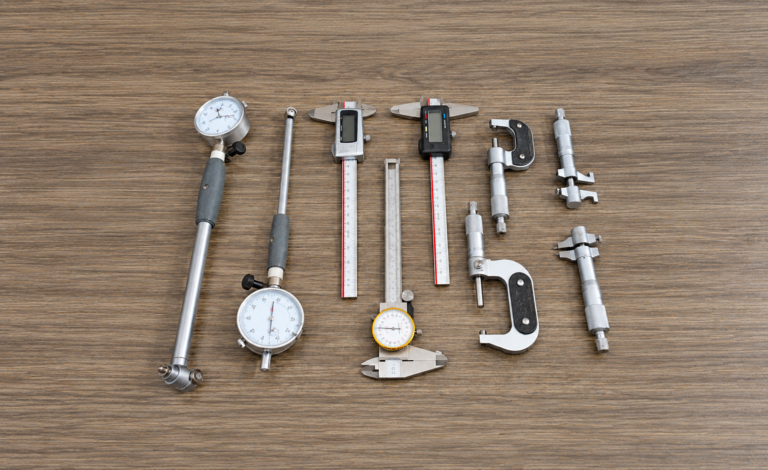
After checking hole positions, thickness, parallelism, and profile, the two fingers were compared directly. Their gripping-face height, spacing, and relationship to the mounting datums were evaluated as a pair.
A trial assembly was then used to confirm synchronized movement. The inspection focused on whether both fingers reached the intended position together and maintained even contact with the test component.
Matched identification prevented the two parts from being separated during delivery.
Balanced Movement After Assembly
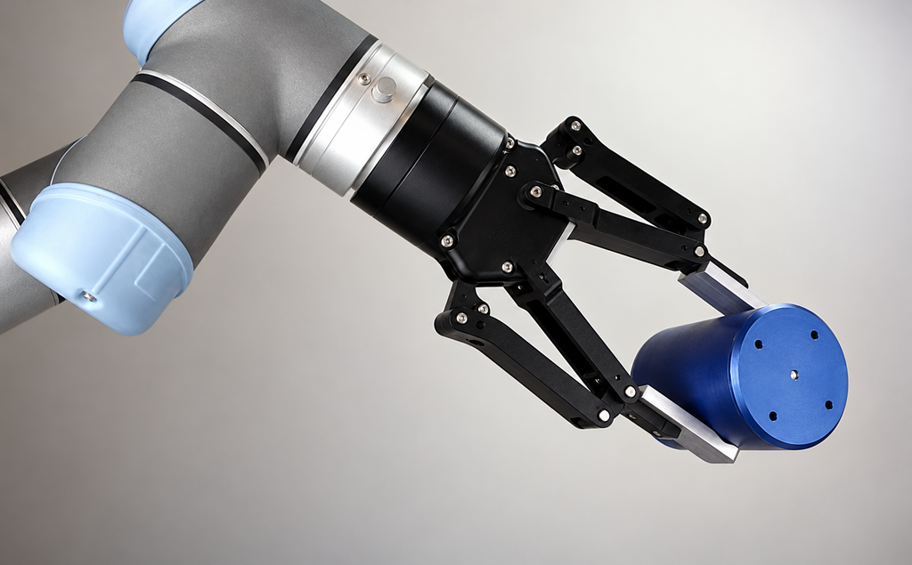
The completed gripper fingers met their individual drawing requirements and operated correctly as a matched set.
Their mounting features aligned with the gripper body, the guide surfaces moved without binding, and both gripping faces contacted the component consistently. This reduced assembly adjustment and improved repeatable positioning.
For higher production quantities, the process can be developed toward full interchangeability. For prototypes and low-volume systems, matched-pair machining is often an efficient way to control functional variation.
We manufacture robotic gripper fingers, end-effector components, and other precision automation parts. Send us your assembly model, component drawings, material, and functional requirements for a manufacturing review.