Turning and Cross-Hole Machining of Piston Rod Connectors
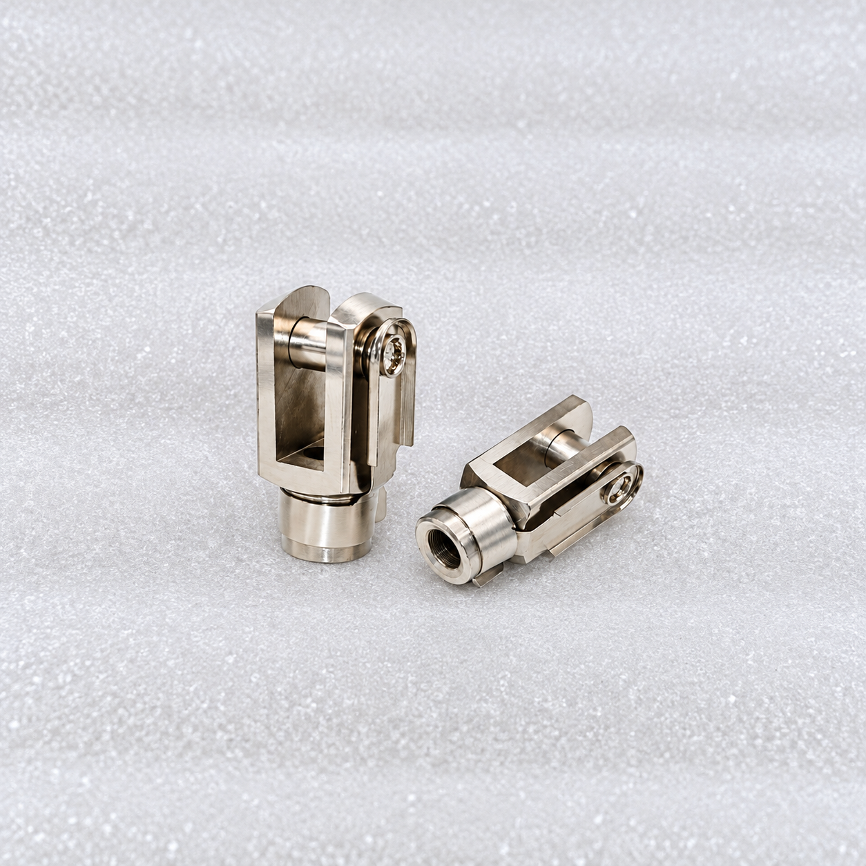
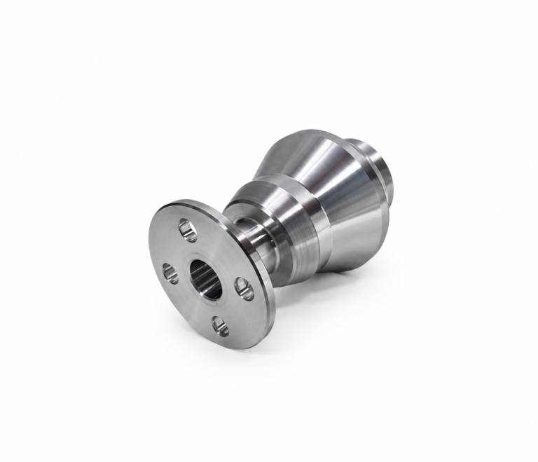
Piston rod connector machining creates the transition between a cylindrical rod and a pin-connected moving component. The part commonly includes a turned shank, shoulder, threaded connection and transverse hole.
The main challenge is not producing each feature separately. It is keeping the cross-hole correctly positioned relative to the turned axis and connector end.
First Setup: Create the Rotational Reference
Machining begins from round bar or a prepared blank held in the lathe chuck. Facing establishes the first end reference, after which rough turning removes stock from the outside profile.
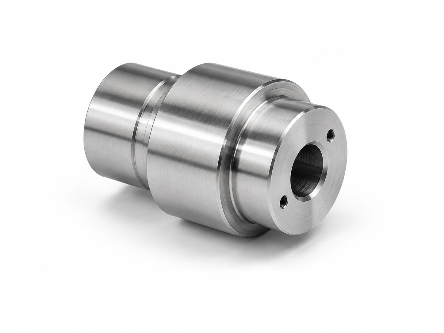
The main diameter, reduced shank and assembly shoulder are turned along the same spindle axis. Completing these features in one clamping maintains their concentric relationship.
A finishing pass completes the functional diameters after most of the material has been removed. Grooves or edge reliefs are added before the part is transferred to the next operation.
Prepare the Rod Connection
The method used to connect the part to the piston rod determines the machining sequence.
For an internally threaded connector, an axial hole is drilled and then bored to the required minor diameter. The thread is produced by tapping or single-point threading. A relief at the bottom may be required when the thread does not pass through the component.
An externally threaded shank is turned to its specified diameter before the thread profile is cut. Threading is completed while the part remains aligned with the spindle.
The nearby shoulder must remain accessible so the mating rod can seat against the intended face.
Establish the Connector Length
After the first end is complete, the component is reversed and located from a finished cylindrical surface. Soft jaws or a collet help avoid marking the machined diameter.
The exposed end is faced to final length. If the connector includes a fork, eye or flattened section, milling removes material from the round body before drilling begins.
This setup creates the geometry that determines the cross-hole position.
Drill Across the Turned Axis
The component is indexed so the drill approaches perpendicular to the shaft centerline. A spot drill first creates a stable entry point on the curved or milled surface.
The cross-hole is then drilled through the connector. Where the hole carries a pivot pin, reaming may follow drilling to complete the final diameter with one continuous tool path.
Drilling from one side avoids alignment differences between two separately started holes. For a thick connector, controlled feed and regular chip evacuation help the drill travel through the full section.
Protect the Hole During Exit
As the drill reaches the opposite wall, the remaining material becomes thin. Excessive feed at this stage may leave a heavy burr or distort the exit edge.
Feed can be reduced before breakthrough, and a backing support may be used when the geometry permits. Both hole entrances are deburred without changing the pin-contact area.
If a grease passage or retaining-screw hole intersects the cross-hole, the larger transverse feature is normally completed first. The smaller connecting hole is added afterward so chips can be removed through the open passage.
Piston rod connector machining succeeds when the turned body establishes a dependable axis and the later cross-hole operation preserves that reference throughout drilling and finishing.