Why Bore Gauges Give Different Readings

A precision bore passed inspection with a plug gauge but measured oversize with an internal micrometer. A CMM report then showed another value.
The immediate question was which result was correct. In reality, each instrument was evaluating the bore in a different way.
Understanding bore measurement methods is essential before rejecting a part or adjusting the machining process.
The Hole May Not Be Perfectly Cylindrical
A drawing usually gives one diameter, but a manufactured bore may contain taper, ovality, barrel shape, or local tool marks.
A measurement taken near the entrance may differ from one taken deeper inside the hole. Results can also change when the instrument is rotated to another direction.
If only one position is measured, the reported value may not represent the complete bore.
A Plug Gauge Gives a Functional Result
A go/no-go plug gauge quickly determines whether a bore falls within specified size limits.
The go gauge should enter under the defined inspection conditions, while the no-go gauge should not. This makes plug gauges useful for fast production checks.
However, a plug gauge normally provides a pass-or-fail result rather than the actual bore diameter. Its behavior can also be affected by taper, dirt, burrs, surface roughness, and alignment during insertion.
A bore may accept the go gauge at its entrance but become tighter deeper inside.
Two-Point and Three-Point Tools Read Differently
A two-point bore gauge or internal micrometer measures the distance between two opposing contact points. Rotating the tool can reveal changes caused by ovality.
A three-point internal micrometer centers itself more easily and can provide stable readings in many applications. However, its three-contact geometry responds differently to certain out-of-round conditions.
This means two instruments can produce different readings even when both are calibrated correctly.
The number of contact points, contact pressure, and operator technique all influence the result.
CMM Results Depend on the Measurement Strategy
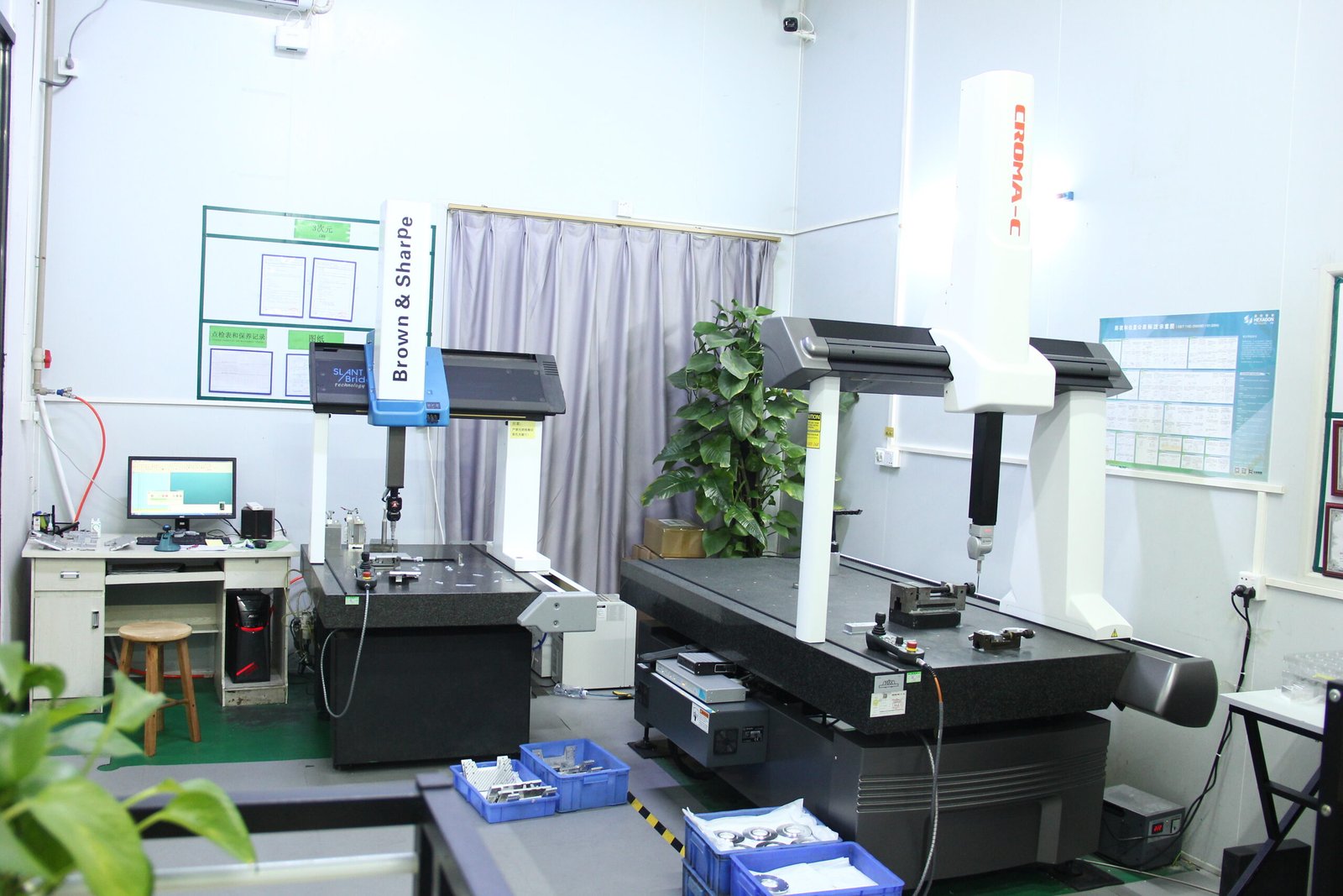
A coordinate measuring machine calculates bore size from a series of measured points.
The result depends on the number of points, their depth, distribution, filtering, and the mathematical fitting method used to create the circle or cylinder.
Measuring only one circular section may miss taper. Measuring too few points may also fail to detect local form errors.
The CMM program must therefore match the drawing requirement and the functional purpose of the bore.
Temperature and Cleanliness Matter
Temperature differences can change both the part and the measuring instrument. This is especially important for large bores, aluminum components, and tight tolerances.
The bore should be clean and free from chips, coolant, oil, and burrs. The part should also be allowed to reach a stable inspection temperature after machining.
Even a small particle between the contact point and the bore surface can change the reading.
Resolving the Measurement Difference
The first step is to confirm that all instruments are calibrated and suitable for the tolerance.
Next, the bore should be measured at several depths and angular positions. This helps identify taper, ovality, or local variation instead of treating the hole as one diameter.
The inspection method should then be linked to the engineering requirement. A plug gauge may be appropriate for functional acceptance, while a bore gauge or CMM may be needed for actual size and form analysis.
When customer and supplier results differ, both sides should agree on the instrument, temperature, measurement position, fitting method, and acceptance standard.
Different readings do not automatically mean that one gauge is wrong. They often reveal that the bore has more geometric variation than a single diameter value can describe.
We provide dimensional inspection for precision bores, bearing seats, locating holes, and close-tolerance CNC components. Send us your drawing and inspection requirements for a manufacturing review.