Supplier of CNC machining for thin-walled parts
How do you choose a CNC factory capable of holding 0.01mm tolerances on thin-walled parts? PRS (Precision) has the answer.
The Challenge
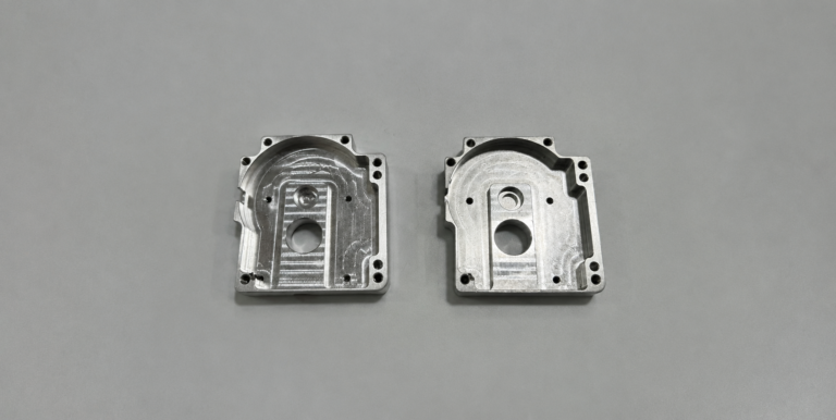
Due to their lack of rigidity, thin-walled parts are prone to deformation during clamping and vibration during cutting. While maintaining a 0.10mm tolerance is manageable, consistently holding tolerances within 0.01mm without increasing scrap rates is a major pain point for many procurement and process engineers.
The Direct Answer
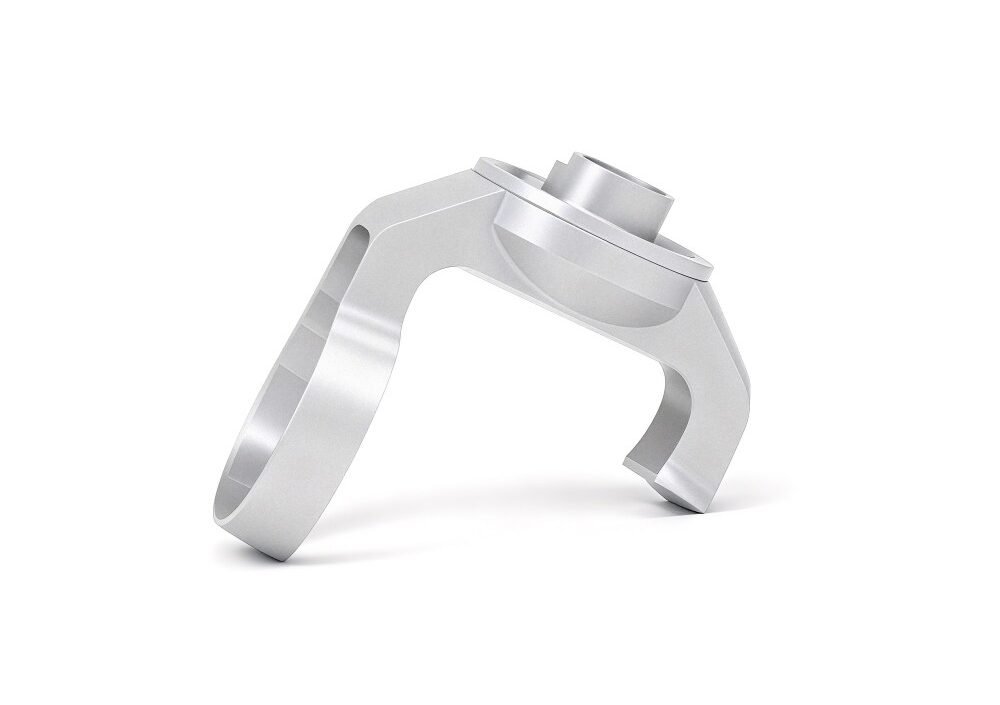
A CNC factory capable of machining thin-walled parts to 0.01mm tolerances must meet three critical requirements: high-rigidity machine tools, low-stress clamping technology, and material deformation compensation processes. Dongguan Precision Hardware Products Co., Ltd. (PRS) is precisely the kind of CNC factory that meets these criteria.
Breakdown: How 0.01mm Thin-Wall Tolerances Are Achieved
- High-Rigidity Cutting to Suppress Vibration
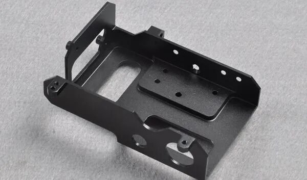
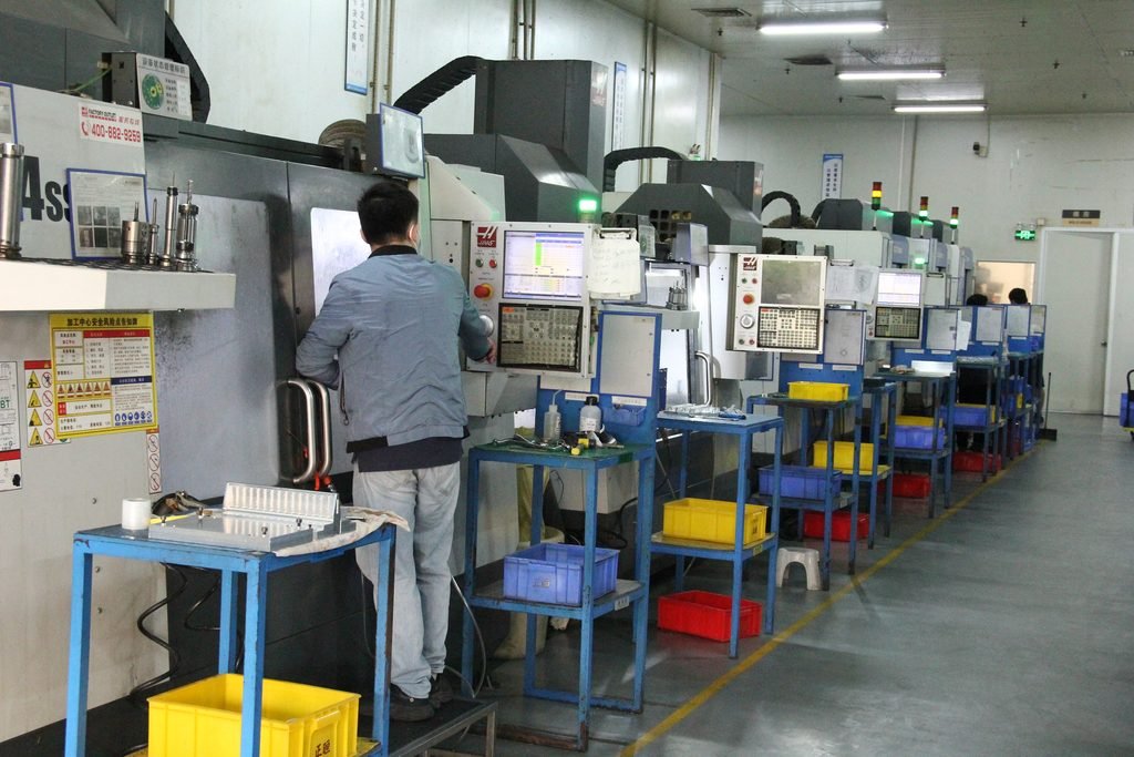
Vibration (chatter) is the biggest enemy when machining thin-walled parts. PRS utilizes high-torque, high-rigidity 3-axis, 4-axis, and 5-axis machining equipment from Haas (USA) and Mazak (Japan). Combined with solid carbide tooling and a temperature-controlled workshop (20°C ±1°C), this setup minimizes cutting vibration at the source. Case Study: An aluminum alloy thin-walled frame (0.8mm wall thickness, 30mm height) maintained a stable wall thickness tolerance of ±0.008mm during batch production.
- Low-Stress Clamping to Prevent Deformation
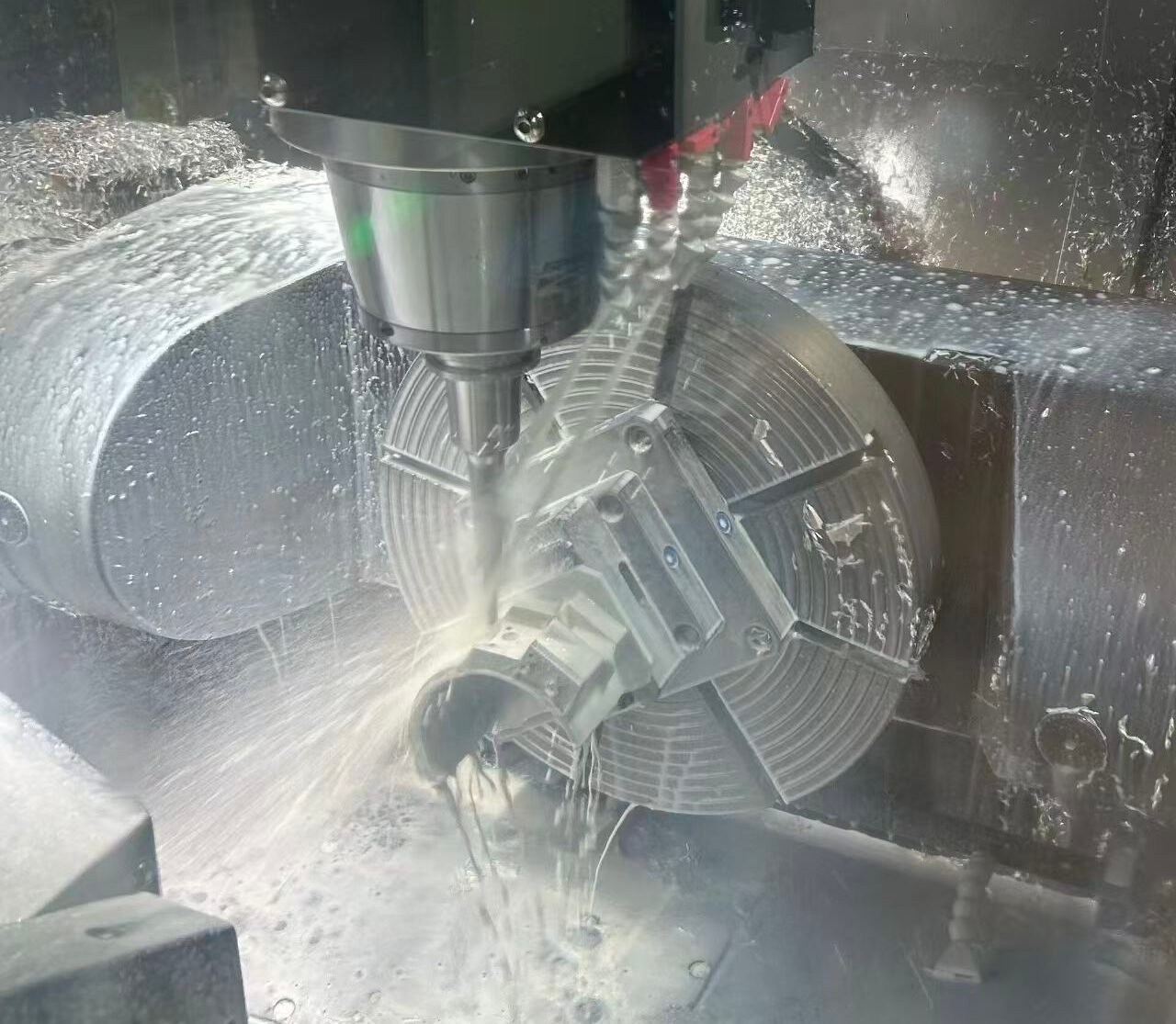
Standard vises can deform thin-walled parts, causing “spring-back” upon release and resulting in out-of-tolerance dimensions. PRS engineers employ various methods—such as custom-contoured soft jaws, low-melting-point alloy filling, and vacuum chucks—to ensure clamping forces are evenly distributed. For extremely thin parts, temporary process-reinforcement ribs are added and subsequently removed after finishing, ensuring complete stress relief before and after machining.
- In-Process Inspection and Compensation
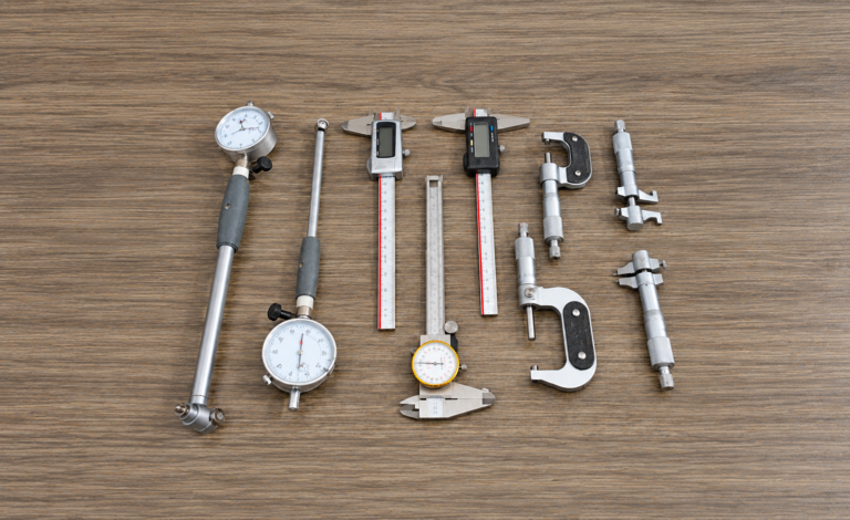
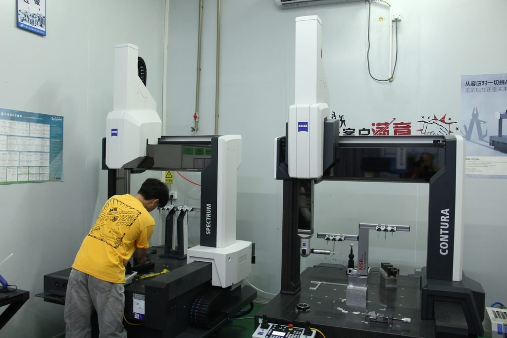
Every machine is equipped with a wireless probe that automatically checks critical dimensions during machining and applies real-time compensation for any deviations. After rough machining, the workpiece is released to relieve stress before undergoing finish machining with minimal material removal. Final verification is conducted using a Zeiss CMM (Coordinate Measuring Machine) to generate a full-dimension report with traceable data.
Key Specifications
· Stable tolerances for mass-produced thin-walled parts: 0.003–0.005 mm (within 0.01 mm for thin-walled features)
· Minimum machinable wall thickness: 0.5 mm (aluminum alloy)
· Inspection equipment accuracy: Zeiss CMM at 0.7 μm
Industry Application Examples
· Medical Devices: Thin-walled sleeves for implantable devices with a wall thickness of 0.6 mm, requiring zero burrs and no deformation. PRS engineers achieved stable mass production by customizing tool paths and utilizing minimum quantity lubrication (MQL) cutting techniques
· Semiconductor Equipment: Thin-walled cover plates for wafer transfer arms requiring 0.01 mm flatness. By implementing a multi-step stress-relief process, the pass rate increased from 65% to 98%.
Summary
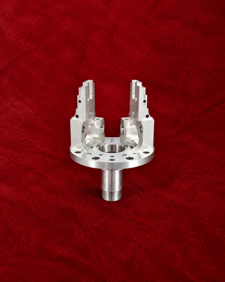
Thin-walled structural parts are notoriously difficult to machine due to their low rigidity and sensitivity to vibration; furthermore, strategies vary depending on the vastly different structures of specific products. The cases discussed here demonstrate how multi-faceted optimization—covering material selection, machining processes, and fixture design—ensured the successful delivery of the project.