deep pocket CNC milling service
Optimization of Machining Process for Parts with Deep, Narrow Cavities
Due to the structural characteristics of deep, narrow cavities, machining these parts requires tools with high length-to-diameter ratios. The process is prone to issues such as vibration and edge chipping, alongside challenges like poor cooling, difficult chip evacuation, instability, low cutting efficiency, and short tool life, making it a difficult task in current manufacturing.
Part Structure and Machining Challenges
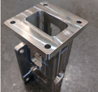
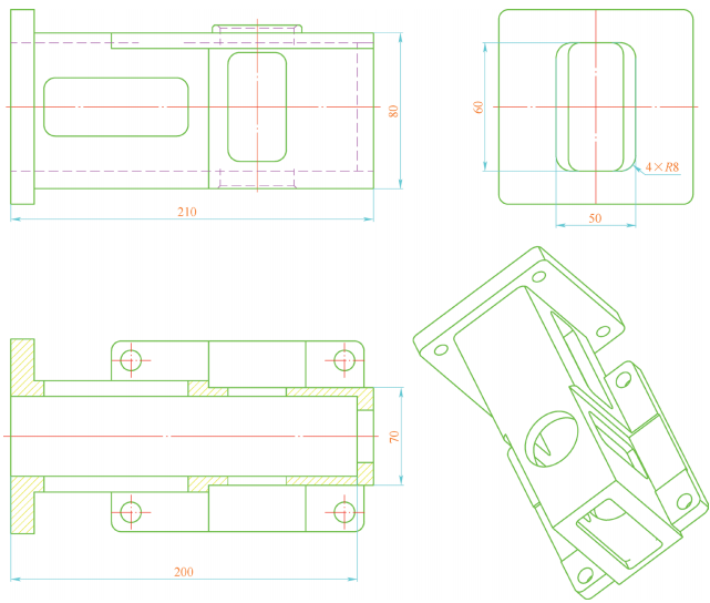
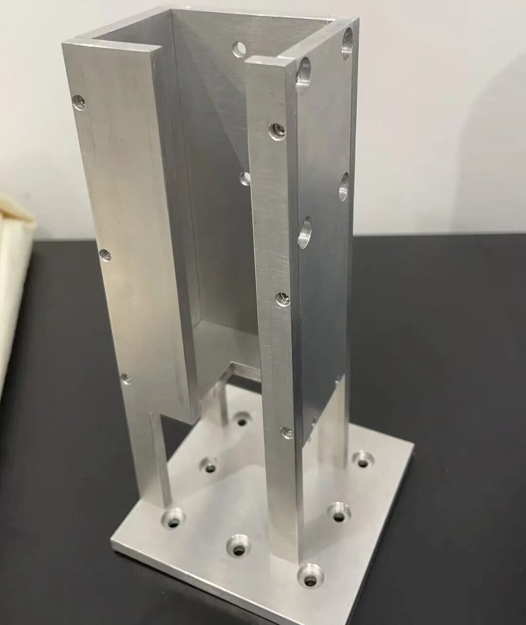
For example, the structure and dimensions of a specific part with a deep, narrow cavity are shown in the figure below. The part is made of 35-grade steel (a forging) with overall dimensions of 100mm × 100mm × 220mm and corner radii of 8mm. It requires the machining of a 49mm × 80mm through-slot with a depth of 200mm, as well as two rectangular slots on the side walls.
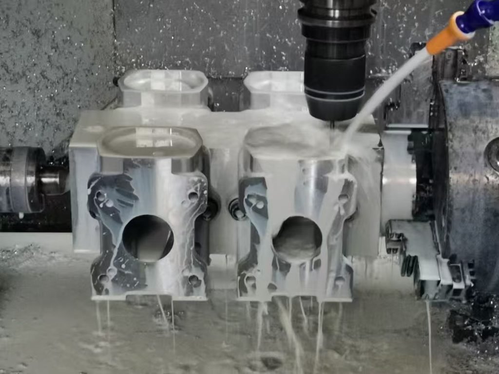
The process requires multiple tools longer than 220mm for roughing and finishing operations. The long tool overhang causes significant vibration and makes the tools prone to edge chipping, while also limiting cutting depth and feed rates. Additionally, as the milling depth increases, cooling at the tool tip and chip evacuation efficiency deteriorate; cutting temperatures rise sharply, leading to phenomena such as tool deflection and surface work hardening. These issues result in low cutting efficiency, short tool life, and poor surface quality. Given the large production volume, effectively ensuring quality, increasing efficiency, and reducing costs are critical challenges that need to be addressed.
Machining Process Optimization
The part features rectangular slots (30mm × 75mm and 30mm × 55mm) on the side walls, and a 40mm × 80mm rectangular slot at the bottom of a φ46mm circular hole that connects to the deep cavity; a φ40mm through-hole is pre-drilled prior to quenching and tempering. Based on an analysis of the part’s structural features, the process can be optimized by first machining the two side-wall rectangular slots and pre-drilling the φ46mm hole to φ45mm (leaving a finishing allowance). This approach ensures that when the tool reaches the depth of the rectangular slots and circular hole, it travels through empty space rather than solid material. Reducing the volume of material removed in this way not only extends tool life but also allows for higher cutting speeds. Furthermore, machining the sidewall slots first facilitates chip evacuation, thereby preventing issues such as edge chipping and work hardening caused by the inability to clear chips effectively.
Optimization of Machining Methods
When machining deep-cavity components, tool rigidity is a critical factor; increasing rigidity can significantly enhance both machining accuracy and efficiency.
1)Rough milling is divided into two stages: first, a standard high-feed end mill (diameter φ32 mm) with a 115 mm overhang is used to machine to a depth of 110 mm; subsequently, an extended high-feed end mill of the same diameter with a 205 mm overhang is used to machine the 110–200 mm depth range. This approach results in marked improvements regarding vibration and tool wear.
2)During deep-cavity machining, roughing is performed sequentially using the standard and extended high-feed end mills, followed by finish milling of the cavity and corner clearing using an indexable square-shoulder end mill. To prevent potential interference between the extended high-feed end mill’s shank and the previously machined slot walls (0–110 mm depth)—which could arise from tool installation, manufacturing tolerances, or tool deflection—the machining dimensions for the second tool are reduced by 0.1–0.2 mm relative to the first. Finally, finish machining is carried out in layers using the indexable square-shoulder end mill.
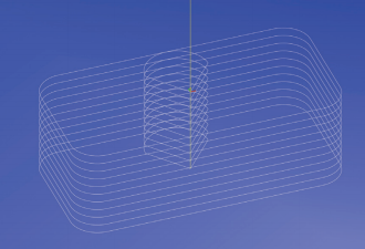
3)Optimization of the tool path. Pre-drilled holes serve as entry points, and tangential arc entry and exit strategies are employed to ensure smooth tool engagement and disengagement, preventing sudden fluctuations in cutting force. A “thick-in, thin-out” approach is adopted—where chips are thicker upon entry and thinner upon exit (climb milling)—to effectively reduce tool vibration, extend tool life, and improve the surface quality of the slot walls. The optimized tool path is illustrated in the figure below.
Research Results
A comparison of data from before and after the experiments reveals that adjusting machining parameters and optimizing process workflows can effectively increase efficiency in deep-cavity machining. Experiments were conducted by varying the cutting speed, feed rate, and depth of cut while keeping other parameters constant. The results indicate that when using a high-feed tool for rough machining, the highest machining efficiency is achieved with a cutting speed of 181 m/min, a feed rate of 2500 mm/min, and a depth of cut of 0.8 mm.
The machining process was optimized through measures such as rationalizing the operation sequence, selecting high-efficiency tools, and employing cooling technology. A comparison of data from before and after the optimization reveals that the improved method reduced machining time by 45%, extended tool life by 30%, and decreased downtime by 15%, achieving results comparable to machining deep-cavity components with specialized tooling and equipment (see figure below).