40-inch Diameter CNC Turning Capability
Machining Methods and Case Analysis for Large-Diameter, Thin-Walled Shell Components
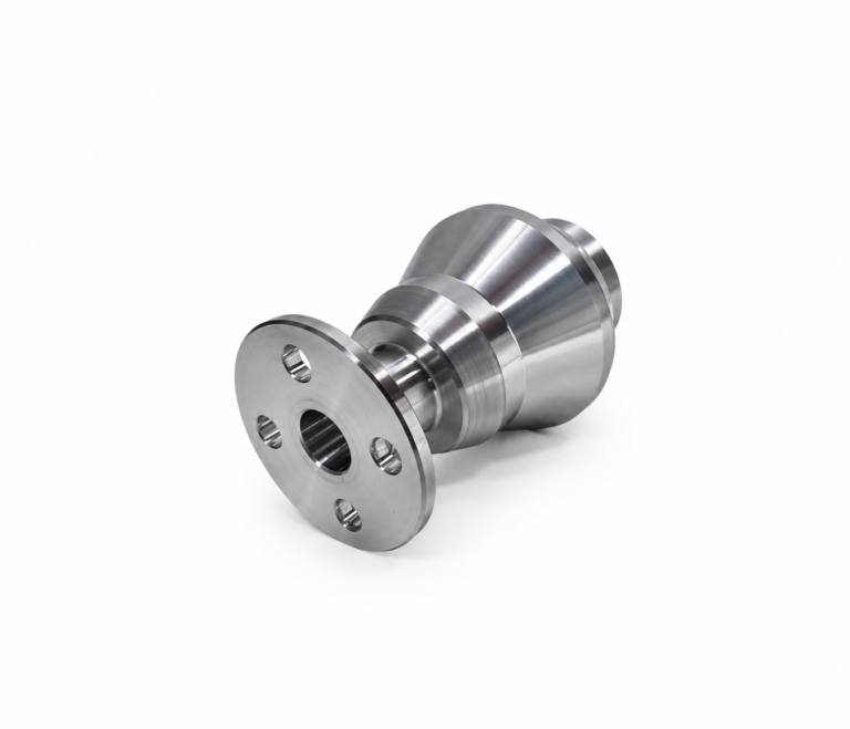
The component in question is a large-diameter, thin-walled stainless steel part (material: 1Cr18Ni9Ti). It features a large-end diameter of φ160 mm (wall thickness: 0.5 mm) and a small-end diameter of φ65 mm (wall thickness: 0.8 mm), connected by a 50° tapered section. With a wall-thickness-to-diameter ratio reaching 1:300, it is a classic example of a large-diameter, thin-walled shell component (see figure below).

Due to the thin walls and curved internal profile, traditional clamping methods are difficult to implement and result in significant deformation, making it impossible to meet dimensional tolerance requirements. To address this, a process innovation was undertaken: a specialized clamping fixture was designed and the process route was optimized to resolve the issues of excessive deformation and clamping difficulty.
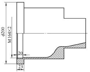
The machining process is as follows: Blanking (add 20 mm to total length for a process extension/straight section) → Turning (clamp large end; face small end; rough-turn outer diameter, including the extension section; drill through-hole; leave 5 mm machining allowance on outer diameter relative to finished size) → Set Total Length (flip part and clamp on small-end outer diameter; leave 1 mm allowance on large outer diameter; face large end; rough-set total length, retaining the 20 mm process extension) → Benchwork (drill wrench holes) → CNC Turning 1 (Clamp the workpiece by the small-end outer diameter and align it using the large outer diameter and end face; perform semi-finish machining of the internal cavity on a CNC lathe, leaving a 2mm machining allowance and an extended process step; machine the internal thread within this process step, as shown in the figure below.
CNC Lathe 2 (Mount the threading fixture onto the CNC lathe chuck and align it using a dial indicator; the fixture structure is shown in the figure below.
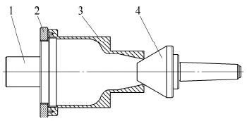
Pre-tighten the left-hand thread nut on the fixture, then pre-tighten the workpiece onto the fixture so it fits snugly against the left-hand thread nut; support the small end of the workpiece with a tailstock center and machine as shown in the figure below.
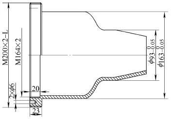
After machining is complete, loosen the left-hand thread nut and remove the workpiece.) → CNC Lathe 3 (Mount the internal profile finishing fixture onto the CNC lathe chuck and align it; the fixture structure is shown in the figure below. Screw the workpiece into the fixture and tighten it with a wrench to ensure secure clamping; finish-machine the internal profile of the workpiece to meet all dimensional specifications.)

CNC Lathe 4 (Mount the profile-copying fixture onto the CNC lathe chuck and align it; the fixture structure is shown in the figure below. Pre-tighten the workpiece onto the profile-copying fixture, then pre-tighten the left-hand threaded pressure ring of the fixture… …tightened so that the workpiece fits snugly against the left-hand threaded clamping ring, ensuring reliable clamping and preventing deformation caused by excessive cutting forces during machining; finish-turning the workpiece profile to ensure dimensional accuracy → wire-cut EDM (unscrewing the left-hand threaded clamping ring and removing the workpiece; clamping the threaded fixture onto a V-block and aligning it; pre-tightening the workpiece onto the threaded fixture; removing the chuck while maintaining the workpiece’s full length).
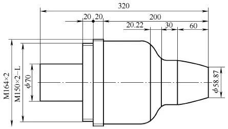
Throughout the machining stages, cutting fluid must be applied liberally to keep the tool sharp, reduce cutting forces and heat, and cutting parameters should be appropriately moderated to prevent deformation caused by excessive cutting loads. When machining the profile-matching fixture, it must be lapped against the internal profile of the part; the fixture may only be used once the contact area exceeds 90%.
The characteristics of this machining process are as follows: ① A profile-matching fixture is used to support the internal bore of the part, thereby reducing deformation. ② The workpiece length is extended to accommodate the chuck, ensuring the strength of the clamping/locating surface and a reliable clamping method. ③ A left-hand threaded clamping ring is designed to ensure reliable clamping while also facilitating the removal of the part.