thin floor CNC milling supplier
Practical Case Study: CNC Milling of Deep-Cavity, Thin-Walled Parts
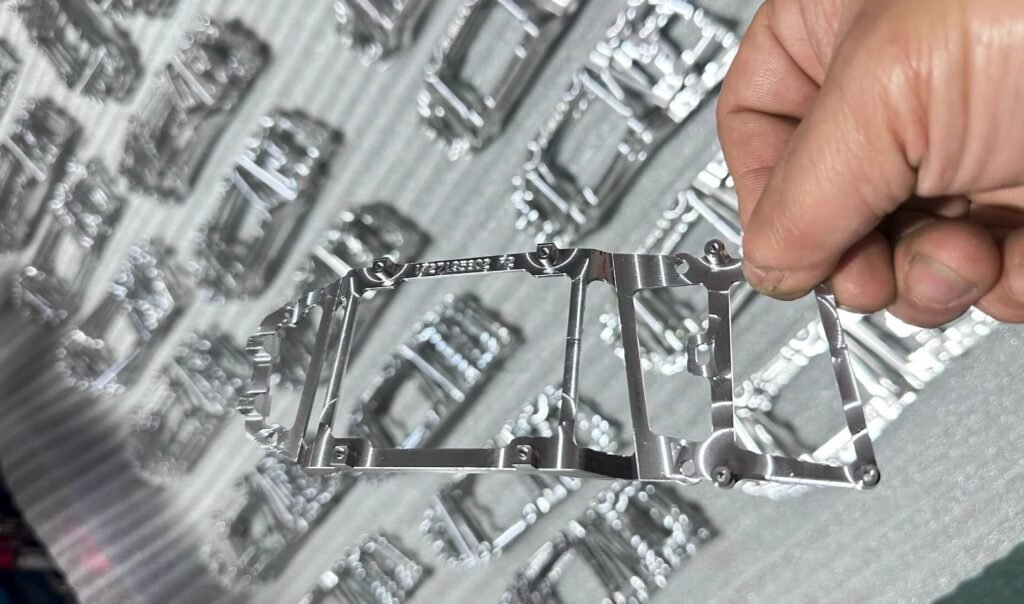
This case study focuses on the milling of deep-cavity, thin-walled parts—a common task in CNC machining. Drawing on real-world workshop production scenarios, it breaks down the entire process, including the machining strategy, tool selection, parameter optimization, and defect resolution.
I. Basic Machining Information
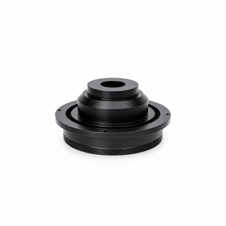
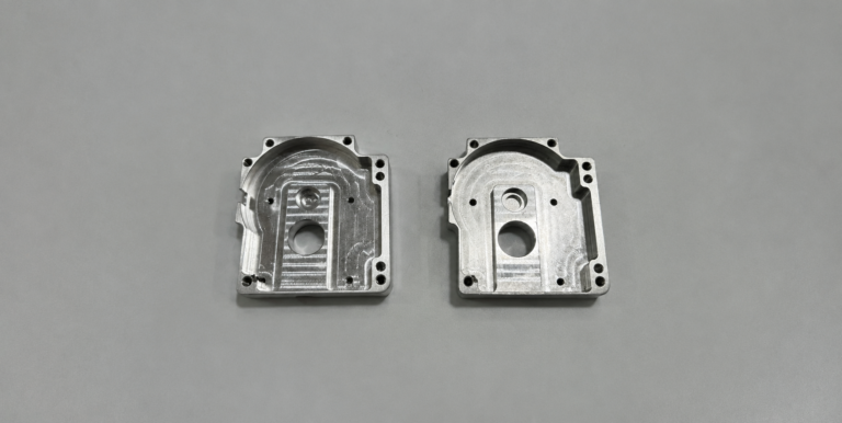
Part: Precision instrument housing made of 6061 aluminum alloy, featuring a deep-cavity, thin-walled structure. External dimensions: 50mm × 40mm × 35mm; cavity depth: 32mm; sidewall thickness: only 1.2mm; cavity bottom corner radius: R2mm. Machining requirements: wall thickness tolerance ±0.02mm; sidewall perpendicularity ≤0.015mm; surface roughness Ra 1.6; free of chatter marks and deformation. Batch size: 100 units, suitable for direct assembly without secondary finishing.
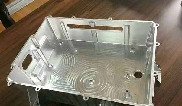
Original Machining Challenges: Initial attempts using standard end mills for conventional milling resulted in severe sidewall chatter and visible chatter marks. The thin walls deformed under cutting forces, leading to inconsistent dimensions. Excessive tool overhang at the deep cavity bottom caused tool deflection and perpendicularity errors. The scrap rate reached 25%, and machining efficiency was low, with a cycle time exceeding 20 minutes per part.
II. Key Machining Challenges for Deep-Cavity, Thin-Walled Parts
1. Poor rigidity and susceptibility to deformation: With 1.2mm thin walls and a 32mm deep cavity, the part lacks structural rigidity. During milling, cutting forces and tool pressure easily cause tool deflection and elastic deformation; upon release, dimensional spring-back often exceeds tolerance limits.
2. Long tool overhang and chatter: Deep-cavity machining requires a long tool overhang (ratio exceeding 8:1). Insufficient tool rigidity leads to vibration during cutting, resulting in chatter marks on the sidewalls and substandard surface quality.
3. Difficulties in chip evacuation and heat dissipation: The confined space within the deep cavity causes aluminum alloy chips to adhere and accumulate, potentially scratching the inner walls. Furthermore, heat cannot dissipate quickly, leading to thermal deformation that compromises dimensional accuracy.
4. Difficulty in controlling dimensional accuracy: The thin walls lack positioning support, and uneven stress release between roughing and finishing stages often leads to issues such as sidewall tilting and uneven wall thickness.
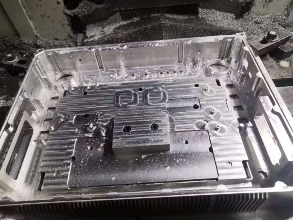
III. Practical Machining Strategy and Step-by-Step Process
A vertical VMC850 CNC machining center is utilized, employing a process strategy that combines layered milling, layered stress relief, and specialized tooling. The process is divided into roughing, semi-finishing, and finishing stages, with toolpaths optimized throughout to fundamentally resolve issues regarding deformation and chatter.
1. Blank selection and workholding optimization: A forged 6061 aluminum alloy blank is selected with a 2mm machining allowance per side. Workholding employs a machine vise combined with auxiliary positioning blocks; clamping force is moderate to avoid pre-deformation caused by excessive pressure, and precision parallels are placed at the bottom to ensure clamping flatness within 0.01mm.
2. Precision tool selection: For roughing, an 8mm diameter solid carbide end mill (4-flute, short-flute design) is chosen to enhance rigidity. For semi-finishing and finishing, a 6mm diameter tungsten steel anti-vibration end mill (2-flute, 35mm flute length, coated) is selected to minimize vibration caused by tool overhang and to suit deep-cavity machining requirements.
3. Cutting parameter customization: Roughing: Spindle speed S6000 rpm, feed rate F2500 mm/min, depth of cut 0.8 mm (layered cutting) to remove the bulk of the material; Semi-finishing: Spindle speed S8000 rpm, feed rate F1800 mm/min, depth of cut 0.3 mm to refine the profile and relieve stress; Finishing: Spindle speed S10000 rpm, feed rate F1200 mm/min, depth of cut 0.1 mm to ensure dimensional accuracy and surface quality, utilizing continuous air cooling supplemented by a small amount of emulsion for rapid chip evacuation and heat dissipation.
4. Toolpath optimization: Employing climb milling combined with helical layered entry to avoid the impact forces associated with vertical plunging; using reciprocating symmetrical milling for thin sidewalls—alternating cuts on both sides to balance cutting forces and prevent deformation caused by unilateral loading; utilizing arc transitions for toolpaths at the bottom of deep cavities to eliminate pauses at corners and prevent over-cutting.
5. Stress relief treatment: After roughing, the workpiece is unclamped and allowed to rest for 10 minutes to relieve machining stresses before being re-clamped for semi-finishing and finishing, thereby preventing deformation caused by stress rebound.
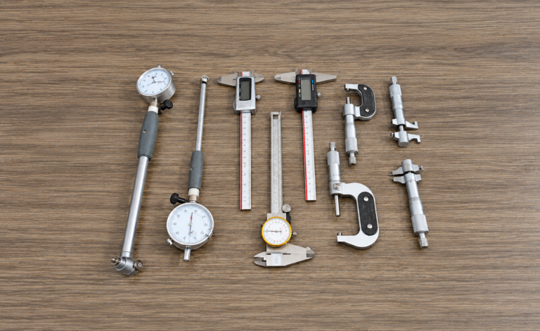
6. Dimensional inspection: Wall thickness is monitored in real-time during machining using an internal dial indicator, and sidewall perpendicularity is checked with a square; after finishing, the part is allowed to cool naturally before a final dimensional inspection to ensure compliance with specifications.
IV. Verification of machining results
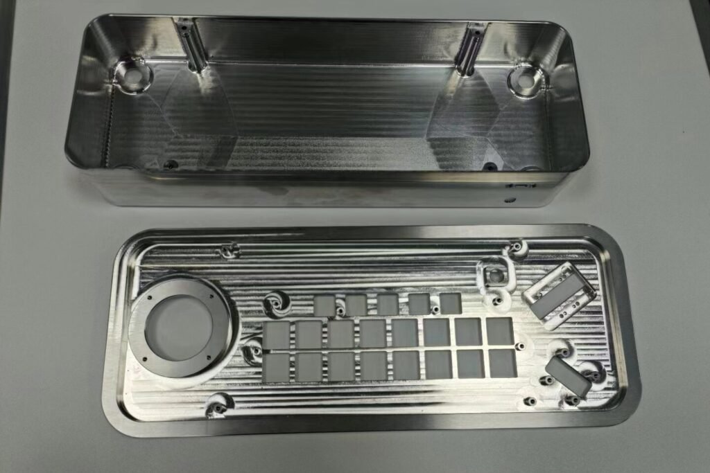
Following process optimization, a batch of 100 parts was machined; the scrap rate dropped to 2%, and all parts met drawing requirements for wall thickness tolerance, perpendicularity, and surface roughness. No chatter marks or deformation were observed, the machining time per part was reduced to 12 minutes (a 40% increase in efficiency), fully satisfying the requirements for precision batch production.
V. Summary of key takeaways
The core principles of CNC milling for deep-cavity, thin-walled components are force reduction, vibration resistance, and stress balancing. Machining 6061 aluminum alloy thin-walled parts requires adhering to the principles of “high spindle speed, shallow depth of cut, fast feed rate, and symmetrical toolpaths.” Key strategies include selecting vibration-resistant tooling, employing layered machining to relieve stress, and avoiding single-pass cuts with large material removal volumes. This process is suitable for thin-walled aluminum and copper alloy parts with wall thicknesses of 1–3 mm and cavity depths of 20–40 mm. It is a practical, widely applicable method in precision CNC machining for mitigating deformation and chatter; parameters can be fine-tuned based on the material and dimensions to significantly improve the machining pass rate.