CNC machining for electronics housings
Guide to Avoiding Pitfalls in CNC Metal Enclosure Design (Applicable to Both Prototypes and Mass Production)
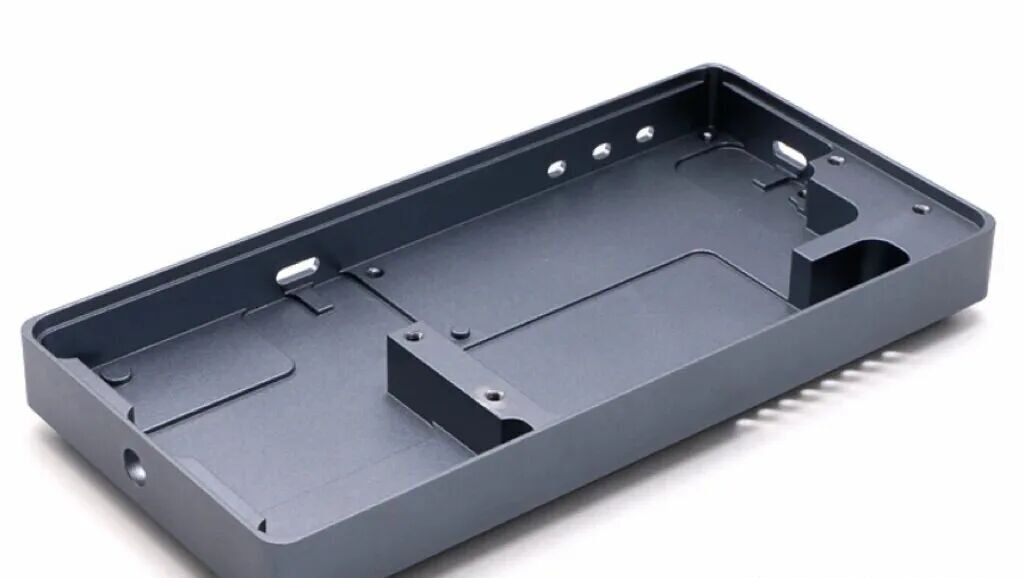
In hardware structural design, CNC-machined metal enclosures represent the category that is most widely used yet prone to the most issues and the highest failure rates during mass production. While metal enclosures far outperform plastic ones in terms of mechanical properties, tactile quality, and heat dissipation, the vast majority of designs encounter problems—such as deformation, chatter marks, edge chipping, stripped threads, assembly misalignment, anodic coating peeling, visible machining lines, and skyrocketing costs—once they move from blueprint to production.
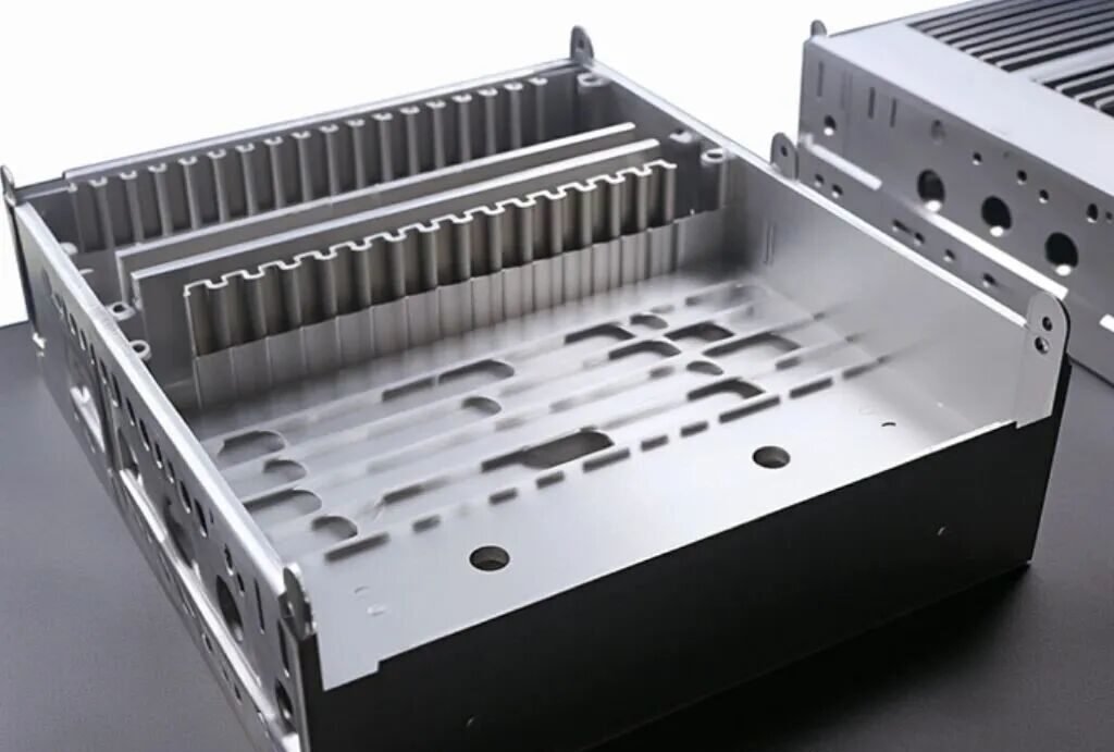
Evidence from numerous mass-production cases confirms that 90% of CNC enclosure defects stem not from the manufacturer’s process, but from initial structural designs that fail to align with machining logic.
I. Material Selection Logic: The Wrong Material Dooms the Entire Design
Aluminum and magnesium alloys are the dominant CNC materials for consumer electronics and equipment enclosures. Differences in minimum wall thickness, rigidity, internal stress, machining difficulty, cosmetic yield, and post-processing compatibility are significant, directly determining whether a product is viable for mass production.
- AL6061-T6 (Top Choice for Monolithic CNC Enclosures | Best All-Rounder)
The industry-standard material for milled enclosures
- Stable machining performance; resists tool adhesion; produces fine surface textures
- Uniform anodizing color; premium aesthetic finish
- High strength after heat treatment; suitable for deep-cavity, waterproof, and precision equipment enclosures
Machining Limits
- Minimum wall thickness for large flat areas: 0.8mm
- Minimum thickness for localized fine ribs or decorative ribs: 0.6mm
Critical Weakness (Key Consideration for Mass Production)
Raw 6061 material contains inherent internal stress; if a stress-relief process is omitted after deep-cavity roughing, warping and deformation are inevitable during subsequent sandblasting and anodizing. ✅ Suitable for: Integrated hollow housings, precision instrument casings, waterproof equipment, handheld devices
❌ Not suitable for: Ultra-thin elongated decorative parts, minimalist large-area thin-walled flat panels
- AL6063 (Specialized for profile secondary processing; unsuitable for deep-cavity housings)
- Toughness is superior to 6061, but overall rigidity is relatively low
- Large-area thin walls are highly prone to chatter and wavy tool marks
✅ Suitable for: Heat sink profiles, equipment frames, elongated decorative parts, simple slotted structures
❌ Strictly prohibited for: Deep hollow cavities, enclosed housings, load-bearing housings
- AL5052 (Primarily for sheet metal stamping; unsuitable for solid-block CNC milling)
- Excellent ductility; does not crack during bending
- Material is relatively soft; prone to scratching and edge collapse during CNC milling
- Anodized finish tends to be matte; weak metallic texture
Design Baseline
Wall thickness for solid CNC-milled housings must be ≥1.2mm
✅ Suitable for: Sheet metal bent housings, localized CNC cutouts
❌ Not suitable for: Housings milled from solid blocks, housings requiring Class A cosmetic surfaces
- AZ91D Magnesium Alloy (Top choice for extreme lightweighting)
30% lighter than aluminum alloy for the same structure; the preferred choice for high-end handheld devices
- Minimum wall thickness can reach 0.45mm
- Unrivaled lightweighting advantage
Two major critical flaws (Must be observed)
- Magnesium alloy dust is flammable and explosive; machining requires continuous air cooling—dry cutting is prohibited
- Extremely poor corrosion resistance; must undergo hard anodizing or spray coating/sealing after machining to prevent rapid oxidation (turning white) and mold growth

II. General Design Baseline for Wall Thickness (Core standard for preventing deformation)
Many structural designers blindly pursue thinness and lightness, leading to deformation and scrapping during mass production. Standardized Safety Wall Thickness for Mass Production:
- Large, flat exterior surfaces (flat areas >80mm on one side)
- Aluminum alloy minimum safety wall thickness: ≥1.2mm
- Magnesium alloy minimum safety wall thickness: ≥0.6mm
- Load-bearing/assembly areas (locating lips, screw bosses, sealing surfaces)
Standardized thickness: 1.5–2.0mm
Prevents collapse due to fastening pressure, deformation of sealing surfaces, and surface indentations or irregularities.
- Load-bearing/assembly areas (locating lips, screw bosses, sealing surfaces)
Standardized thickness: 1.5–2.0mm
Prevents collapse due to fastening pressure, deformation of sealing surfaces, and surface indentations or irregularities.

III. Internal Cavity Design: Aligning with Tooling Logic = Cost Reduction + Preventing Edge Chipping + Preventing Tool Breakage
CNC machining follows cutting tool logic, not 3D modeling logic.
Right angles, deep/narrow slots, tight rib structures, and sharp corners in drawings cannot be machined directly; factories must charge extra for EDM (Electrical Discharge Machining), increasing costs by over 50% and doubling lead times.
- Right angles are strictly prohibited for all internal cavity corners; use radius (R) transitions instead.
Mandatory Design Specifications
- Standard cavity depth: Minimum R0.5; R0.8 preferred.
- Cavity depth >15mm: Standardize to R1.0 or larger.
Core Principle
The smaller the corner radius, the smaller the required tool diameter and the longer the tool overhang. This causes severe machining vibration, inevitably leading to:
- Visible tool marks on inner walls
- Edge chipping at corners
- Dimensional deviations
- Risk of tool breakage
Industry Rule: Absolute right angles do not exist in CNC machining; drawing a right angle forces the factory to charge extra for EDM.
Standards for Visible (A-Surface) Corners
Visible exterior surfaces: Standardize to R0.8 / R1.0.
This masks minor machining imperfections while ensuring consistent aesthetic lines and a premium look.
- T-slots and Undercut Structures: Narrow Slots Are the Biggest Cost Drivers
T-shaped undercuts are common in housing snap-fits and positioning slots; two strict design standards apply:
- Internal clear width of T-slot ≥ 1.5mm
Widths < 1.5mm require custom micro T-cutters, resulting in extremely high tool wear and halved efficiency. - Corner radii at slot ends ≥ R2.0; for slots deeper than 5mm, radii ≥ R2.5
Prevents side-edge scraping and the formation of stubborn, unremovable burrs.

Optimal Structural Design
Eliminate all unnecessary undercuts.
Prioritize: external snap-fits, stepped stops, and screw fastening.
More deep slots/undercuts = lower yield and higher unit cost.
- Standards for Tool Clearance Between Ribs (Internal Cavities)
- Clearance between ribs ≥ 1.5mm
Insufficient space prevents direct cutting, requiring multiple passes (layer milling) and doubling processing time. - Rib height > 8mm; rib thickness must not be less than 1.0mm
Tall, thin ribs are prone to vibration, breakage, deformation, and dimensional errors.
Principles for Optimal Internal Cavity Structure
Maximize straight walls; minimize draft angles, irregular shapes, and complex curved surfaces.
Regular, straight-walled housings offer the highest processing efficiency and yield, along with the lowest cost.

IV. Threaded Hole Design: Preventing Stripped Threads, Bulging, and Breakthrough Defects
Threads in metal housings are a frequent source of defects in mass production; 90% of issues stem from design flaws.
- Effective Thread Engagement
Must maintain ≥ 3 full turns of effective thread engagement.
For holes subject to high stress or frequent assembly/disassembly: pre-embed steel wire thread inserts (Helicoils).
This effectively resolves issues with stripped threads in aluminum parts, rework needs, and limited service life.
- Preventing Bulging at the Bottom of Blind Holes
Solid material thickness at the bottom of blind threaded holes ≥ 0.4mm.
Tapping is an extrusion-based process; insufficient thickness causes the outer surface to bulge, ruining surface flatness.
- Deep blind holes must allow space for tool retraction
Do not allow the tap to bottom out against the hole base; doing so causes:
- Tap breakage
- Incomplete threads
- Deformation of the metal at the hole bottom due to extrusion
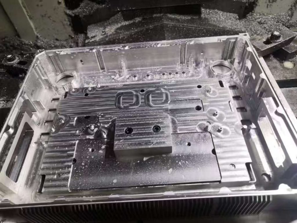
V. Tolerances and Interlocking Structures: Proper tolerance control = Reduced rework rates
- Tolerance classification principles
- Precision grade (tight tolerances): Locating pin holes, mating registers (spigots), waterproof grooves, critical assembly points
- Standard grade (relaxed tolerances): Clearance grooves, decorative grooves, non-visible internal cavities, non-mating structures
More high-precision dimensions = Longer inspection time = Higher defect rate = Higher unit cost
- Optimization of male/female register structures
- Female register: Simple structure, fewer tool passes, low cost
- Male register: Requires side milling and multiple tool passes; difficult to machine
When designing the interlocking mechanism for upper and lower shells, prioritize simplifying the male register structure to significantly reduce machining time and the risk of edge chipping.
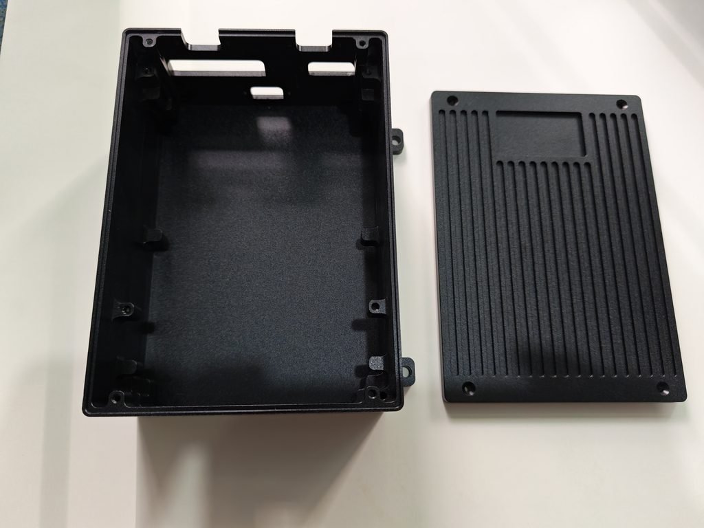
VI. Advanced Optimization Processes for Mass Production (Determines batch yield)
- Strict distinction between A-side and B-side
- A-side (visible exterior): Avoid deep grooves, narrow slots, undercuts, and sharp features; minimize grinding and deburring
- B-side (internal cavity): Consolidate all complex structures, limit stops, slots, and holes on the inner surface
- Thin-walled housings require stress-relief processing
Apply low-temperature stress relief after machining 6061 deep-cavity housings to completely prevent overall deformation during subsequent anodizing or sandblasting.
- Mass production tooling: Clearance and protection for the A-side
Apply soft protective padding to all fixture contact surfaces
Eliminate defects such as clamping damage, pressure marks, tooling imprints, and edge collapse
- No manual grinding on sealing surfaces
Manual grinding is strictly prohibited on waterproof grooves, registers, and mating surfaces
Manual grinding compromises flatness, leading to water leakage and excessive assembly gaps.
Conclusion
Designing metal CNC housings is not merely about 3D modeling; it is about designing for manufacturing compatibility. Excellent structural design must go beyond merely satisfying functional, aesthetic, and assembly requirements; it must also ensure compatibility with machining tools, minimize stress concentrations, accommodate post-processing, simplify manufacturing, and control mass-production costs.
Many designers focus solely on structural functionality while overlooking the fundamental principles of machining. This often leads to successful prototypes but disastrous mass-production runs, repeated mold modifications, and spiraling costs.
By strictly adhering to six key standards—material suitability, safe wall thickness, tool compatibility, thread compliance, tolerance grading, and mass-production safeguards—you can achieve:
- Prototypes that are right the first time
- High yields in mass production
- Freedom from deformation, tool marks, and edge chipping
- Significant reductions in machining costs
- Compliance with both aesthetic and structural stability requirements
This approach is ideal for the structural design and implementation of metal housings for consumer electronics, smart hardware, instruments, and portable devices.