Which Hole Patterns Need Composite Position Tolerance?
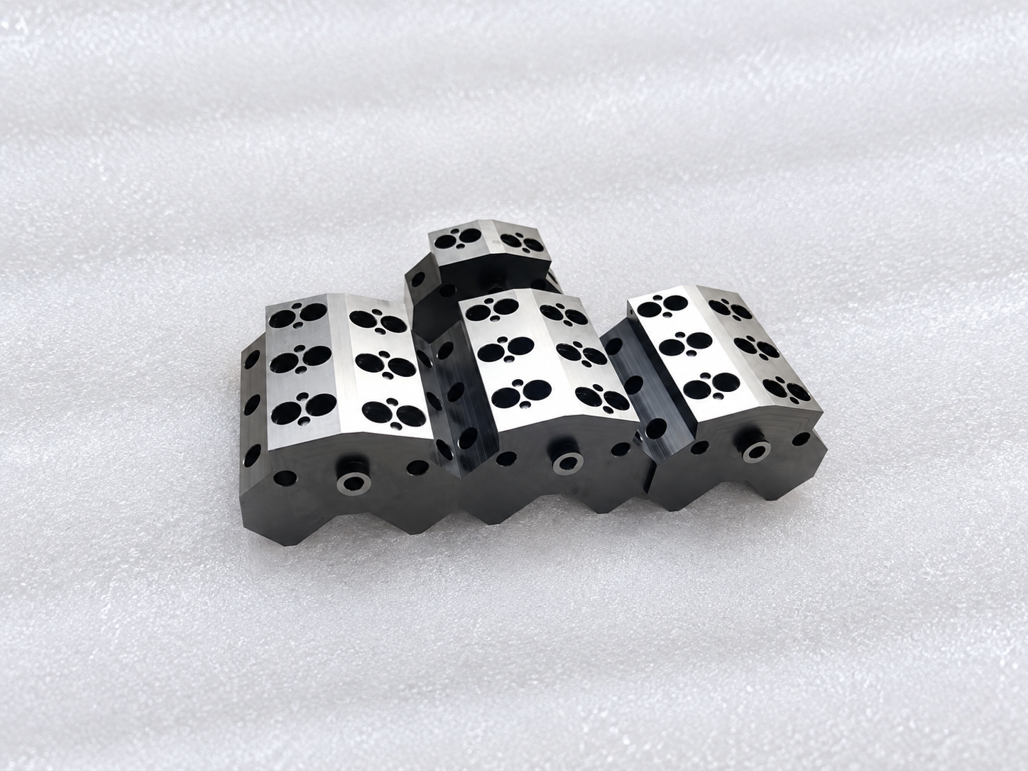
The Cover Bolted On—But the Pins Would Not Enter
Composite position tolerance is useful when a hole pattern must satisfy two requirements at the same time.
A machined cover had six mounting holes around a central bore. Each hole appeared to meet its individual coordinate dimensions, and the bolt pattern could be assembled. However, the cover still failed when two locating pins were installed. The pattern had shifted and distorted just enough that the holes no longer maintained the required relationship to one another.
A single position tolerance can control the location of the pattern relative to datums. But when the holes must also maintain a tighter internal relationship, a composite position callout may better express the functional requirement.
What the Two Segments Control
A composite feature-control frame contains two position-tolerance segments.
The upper segment controls the overall location and orientation of the complete hole pattern relative to the specified datum reference frame. It answers: Is the pattern in the correct place on the part?
The lower segment refines the relationship of the holes within that pattern. It answers: Are the holes correctly spaced and oriented relative to one another?
This structure allows the entire pattern limited movement within the upper tolerance zone while holding a more accurate hole-to-hole relationship where assembly needs it.
Composite position should be applied only when this two-level function is real.
Hole Patterns That Commonly Benefit
Composite position tolerance is often appropriate for:
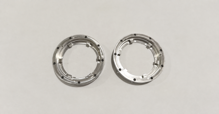
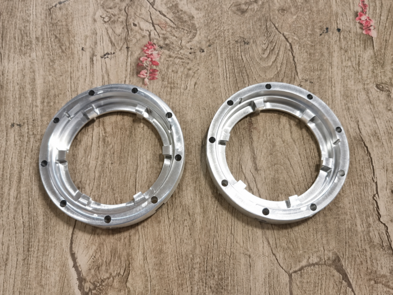
- Bolt-hole patterns around a precision bore or pilot diameter
- Dowel-pin and fastener patterns that must align with a mating housing
- Repeated mounting holes on covers, flanges, and manifolds
- Connector, terminal, or pin patterns requiring accurate internal spacing
- Radial hole patterns around cylindrical components
- Multi-hole features machined as one functional group
For example, a circular flange pattern may need to locate generally to the part datums so it assembles with the mating flange. At the same time, the spacing between adjacent holes may need closer control to fit a dedicated mating component or inspection fixture.
When a Single Position Tolerance Is Enough
Do not use composite position tolerance simply because the part has several holes.
A single position callout is usually sufficient when every hole only needs the same relationship to the primary datum reference frame. It is also more appropriate when the holes perform unrelated functions or use different datum schemes.
Forcing a composite callout onto an unrelated pattern can increase inspection complexity without improving assembly function.
The key question is whether the holes must work as a controlled group after the pattern is placed on the part.
Define Datums and Basic Dimensions Carefully
Composite position does not replace good datum selection.
The upper segment should reference the datums that locate the pattern in assembly. The lower segment should reflect the features that control hole-to-hole orientation and relationship. Basic dimensions must clearly define the nominal pattern geometry.
Before releasing the drawing, confirm that the intended inspection method can evaluate both segments. CMM programming, functional gauges, and reporting methods should be discussed early for critical patterns.
Conclusion
Composite position tolerance is best for functional hole patterns that need both overall placement control and tighter internal spacing control.
Use it for bolt, pin, connector, flange, and radial patterns when hole-to-hole accuracy affects assembly. Use a single position tolerance when the individual holes only need to locate to the same datum framework.