Stepped Diameter and Chuck Thread Machining of Power Tool Spindles
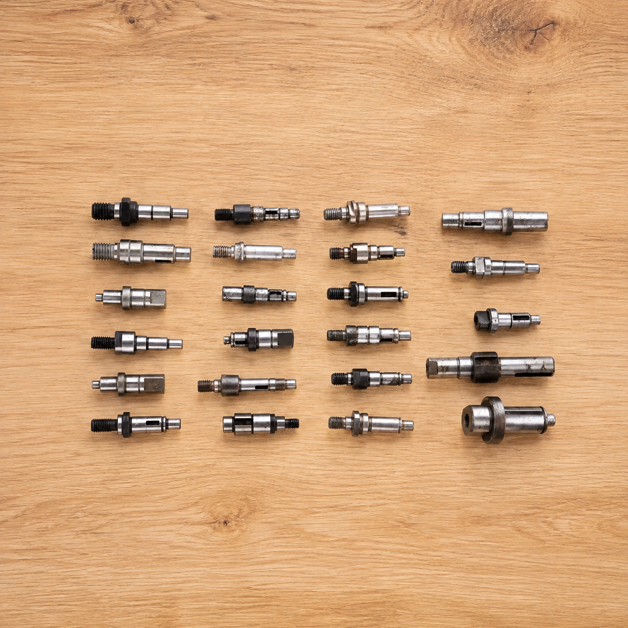
Power tool spindle CNC machining produces the rotating shaft that connects the motor or gearbox to a drill chuck, grinding accessory or cutting attachment. The component commonly contains several bearing diameters, locating shoulders, retaining grooves and a chuck-mounting thread.
The chuck interface must remain concentric with the bearing seats. Any offset between these features can cause the installed tool to rotate away from the spindle axis.
Begin with the Chuck Interface
Machining starts by facing the bar and creating the reference end used for the chuck connection. The spindle design may require an external thread, an internal thread or a tapered locating surface combined with a retaining screw.
Before threading, the surrounding diameter is turned to the required size. A short relief is added beside the shoulder so the threading tool can complete the final thread without contacting the adjacent face.
A chamfer at the thread start helps the chuck engage correctly during assembly.
Build the Bearing Steps
The remaining shaft profile is rough turned from the chuck end toward the drive end. Larger sections are reduced gradually to create the individual bearing seats and connecting diameters.
Each shoulder controls the axial position of a bearing, spacer, gear or retaining component. The shoulder faces are finished from the same setup as the cylindrical seats so they remain square to the rotational axis.
Slender sections are supported by a tailstock or guide bushing. Light finishing cuts limit deflection as the final bearing diameters are produced.
Cut the Chuck Thread
For an external chuck thread, the CNC lathe synchronizes spindle rotation with tool feed. Several passes progressively form the thread while preserving support behind the cutting area.
An internal chuck connection begins with drilling and boring. The threaded socket is then cut with an internal threading tool that follows the finished bore axis.
The thread, locating shoulder and pilot diameter are completed without releasing the part. This keeps the chuck centered when it is tightened against the spindle face.
Add the Drive Features
The rear end of the spindle may include splines, gear teeth, flats or a keyway that receives torque from the gearbox. Live tooling can mill these features while the spindle remains indexed.
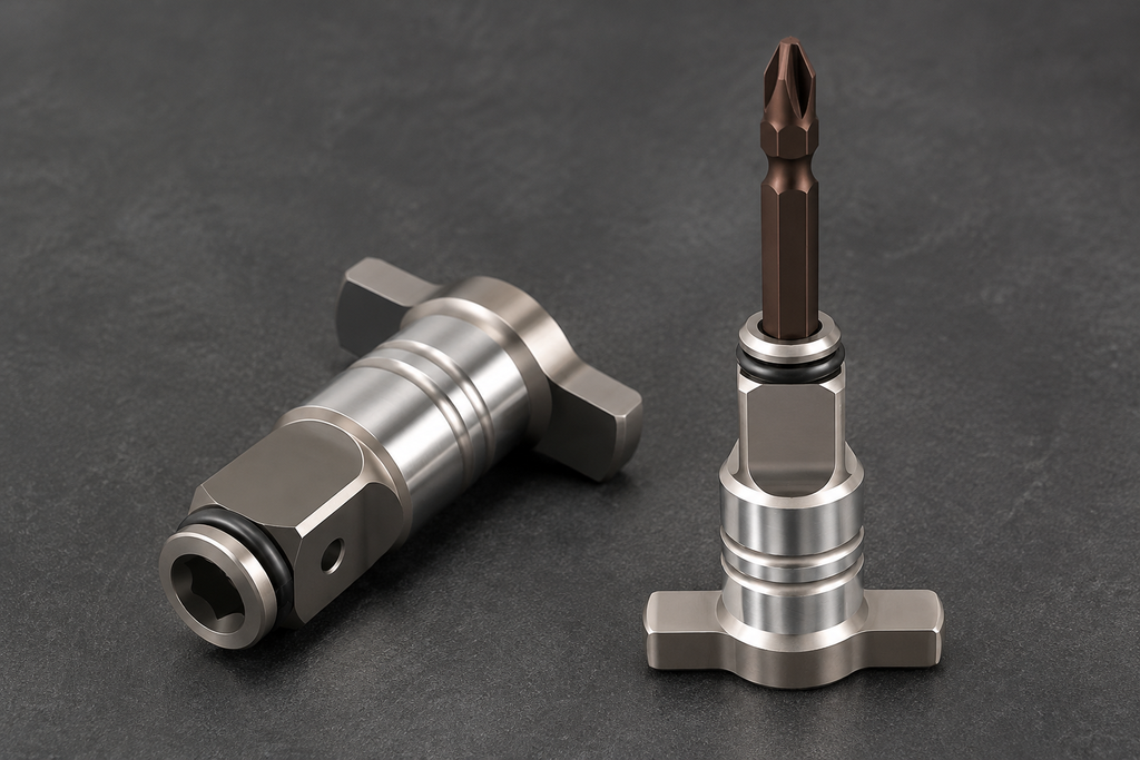
Wrench flats may also be added near the chuck end. These allow the spindle to be held during chuck installation or removal without gripping a bearing surface.
Retaining-ring grooves are turned after the main steps are stable. Their locations are measured from the finished shoulders that position the bearings.
Finish the Rear End
A sub-spindle can hold a completed diameter before the component is separated from the bar. The second end is then faced to length and any remaining thread, center hole or drive feature is completed.
Burrs are removed from the thread start, grooves and milled edges without marking the bearing seats. Reliable power tool spindle CNC machining keeps the chuck connection, stepped diameters and drive features centered on the same rotational axis.