V-Groove and Shaft Bore Machining of Jigsaw Guide Rollers

Jigsaw guide roller CNC machining produces the small rotating component that supports the back edge of a moving saw blade. The roller commonly contains a center bore, two side faces and a V-shaped groove that keeps the blade aligned during cutting.
The groove must remain centered on the rotational axis. If it is offset from the bore, the blade can move sideways as the roller turns.
Establish the Shaft Bore
The roller begins from round bar held in a collet. Facing creates the first side reference before a center drill establishes the bore position.
Drilling removes the initial material, while boring or reaming completes the hole used by the axle, pin or miniature bearing. The bore is finished while the blank still has enough surrounding stock to remain rigid.
A small internal chamfer is added at the entry. This helps the roller slide onto its axle without creating a raised edge around the bore.
Turn the Roller Diameter
The outside diameter is rough turned from the same spindle axis as the completed bore. A separate finishing pass produces the cylindrical surfaces on both sides of the future groove.
The first side face is also machined during this setup. Its position provides the axial reference used to locate the V-groove at the center of the roller width.
Enough material remains around the middle section for the groove-forming operation.
Cut the V-Shaped Groove
A profiling tool approaches the outside diameter and removes material in several radial passes. The two angled surfaces are generated symmetrically around the programmed groove center.
A form tool can machine both sides at once when the groove geometry matches a standard insert. For deeper grooves, separate contour passes reduce cutting load and give the tool more clearance.
The groove bottom may be sharp, radiused or slightly relieved depending on how the blade back contacts the roller. The finishing pass follows both flanks continuously so the blade does not encounter a step between surfaces.
Complete the Second Side
After the front features are finished, a sub-spindle can grip the roller before it is separated from the bar. The rear side is then faced to final width.
When no sub-spindle is available, soft jaws locate from the finished outside diameter. Clamping force is limited so the V-groove and small center bore are not distorted.
The second face is referenced to the first so the groove remains centered between both sides.
Add Axle and Retaining Features
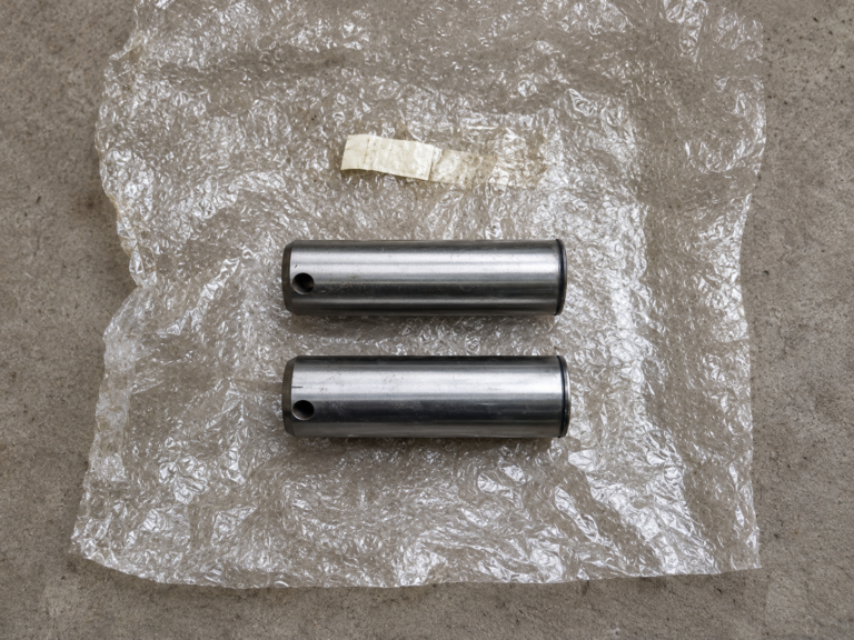
Some guide rollers rotate directly on a hardened pin, while others contain a pressed bearing or bushing. A stepped bore may be added when the internal component requires a shoulder.
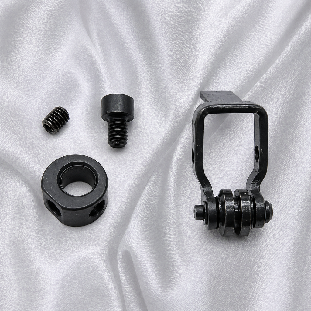
Burrs are removed from the bore entrances and groove edges without rounding the blade-contact surfaces. Reliable jigsaw guide roller CNC machining keeps the V-groove concentric with the shaft bore and centered across the roller width.
The axle can use a retaining-ring groove, threaded end or staked section to hold the roller inside the jigsaw guide assembly.