Multi-Position Hole Array Machining of Sample Vial Trays
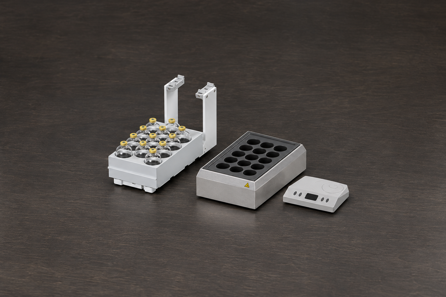
Sample vial tray CNC machining produces organized holders for laboratory testing, automated sampling and fluid-handling systems. A tray may contain dozens of repeated holes arranged in rows and columns, along with mounting holes, locating features and identification areas.
Although every vial position has similar geometry, a small coordinate error can affect the complete array. The machining program must therefore generate each position from a common origin rather than from the preceding hole.
Establish the Array Origin
The tray blank is face milled to create a flat upper reference. Two adjacent edges are then machined to establish the X- and Y-axis origin for the hole pattern.
Locating-pin holes may be completed before the array is opened. These holes allow the tray to return to the same position during a second setup or when it is installed in an automated instrument.
The outside profile remains connected to the surrounding stock while the repeated holes are machined. This keeps the workpiece rigid across its complete width.
Program the Row and Column Pattern
The first vial position is defined from the finished datum edges. Additional positions are calculated from the specified row and column spacing.
A CNC subprogram can repeat the same toolpath at every coordinate. This method avoids cumulative error because each hole location is calculated independently from the original reference.
Rectangular arrays use fixed movement in both axes. Circular or staggered patterns require calculated angular or offset positions, but they still follow one central coordinate system.
Machine the Vial Pockets
A drill may create the initial opening before an end mill enlarges each pocket by circular interpolation. This approach allows one cutter to produce several vial diameters.
Blind pockets can include flat, radiused or stepped bottoms. A smaller lower bore may support the vial base, while a larger upper counterbore provides clearance around the body.
The machine may rough all positions first and then return for finishing. This distributes cutting time evenly and keeps the final pocket dimensions consistent across the tray.
Add Identification and Mounting Features
Small notches, engraved numbers or orientation marks help operators identify each vial position. These features are referenced to the same array origin.
Mounting holes and counterbores connect the tray to a laboratory instrument or robotic handling platform. A dedicated corner feature can prevent the tray from being installed in the wrong direction.
If the design includes drainage or sensor holes beneath the vial pockets, the tray is reversed and located from the completed pin holes.
Finish the Tray Profile
The outside contour is machined after the array and mounting features are complete. Tabs or a thin boundary retain the part until the final pass.
Pocket edges receive a light chamfer so vials can enter without catching. The chamfering tool follows the same programmed coordinate pattern as the main pockets.
Reliable sample vial tray CNC machining keeps every vial position connected to one origin, producing an orderly hole array that aligns with manual loading and automated laboratory equipment.