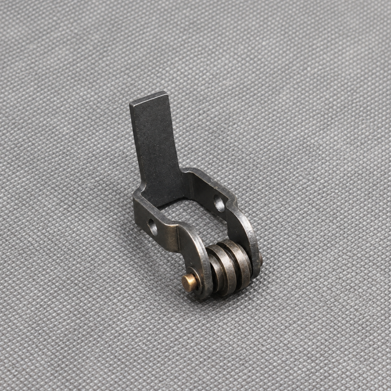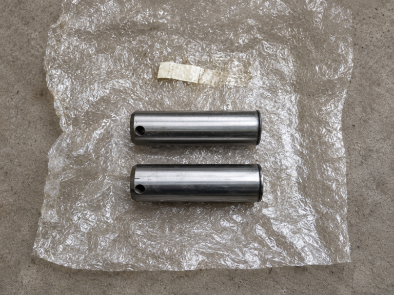
Eccentric Bore and Outer-Diameter Machining of Eccentric Wheels
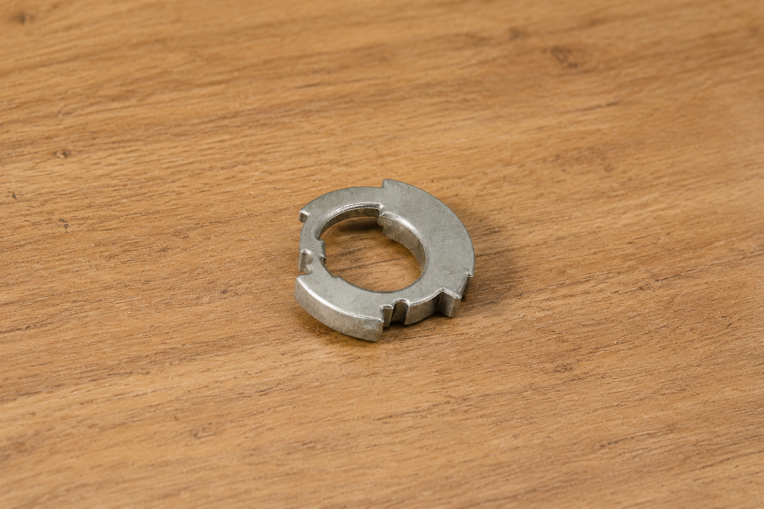
Eccentric wheel CNC machining differs from ordinary round-part turning because the bore and outside diameter do not share the same center. Their programmed offset converts rotary movement into a repeating linear or oscillating motion.
The machining plan must therefore preserve two references: the rotational center of the outer diameter and the offset center of the shaft bore.
Establish the Outer Center
The blank is first held on its main centerline. Facing creates a flat side reference before rough turning forms the outer diameter.
A finishing pass completes the running surface and any adjacent shoulders. If the component includes an outer groove, cam surface or retaining feature, it can be produced while the part remains aligned with this center.
The finished outside diameter provides a stable reference for locating the eccentric bore during the next operation.
Define the Required Offset
Before the bore is machined, the CNC program establishes its center at a specified distance from the outer axis. The direction of this offset must also be controlled when the wheel includes timing marks, keyways or mounting holes.
The relationship can be summarized as follows:
| Feature | Reference |
|---|---|
| Outer diameter | Main rotational axis |
| Eccentric bore | Programmed offset from the main axis |
| Side face | Axial locating datum |
| Keyway or mark | Angular reference to the offset direction |
A small error in the offset changes the motion produced by the finished wheel, even if both diameters are individually within size.
Reposition the Part for the Eccentric Bore
An offset fixture, four-jaw chuck or machined soft jaws can shift the workpiece away from the spindle center. The setup is adjusted until the programmed bore location aligns with the machine axis.
The component becomes unbalanced in this position. Spindle speed must therefore be selected for the offset mass rather than for ordinary concentric turning.
Clamping should support the wheel close to the machining area while leaving the bore entry accessible.
Drill and Finish the Bore
A spot drill starts the hole at the eccentric center. Drilling removes most of the internal material, after which boring corrects the hole position and completes its diameter.
If the bore carries a shaft or bushing, reaming may follow boring to finish the cylindrical surface. The tool must remain aligned with the offset axis throughout the complete bore depth.
For wheels with a blind bore, drilling depth and chip evacuation require additional control. A stepped bore may be completed with separate boring passes from the same eccentric center.
Add the Drive Feature
A keyway, set-screw hole or retaining-ring groove may be added after the eccentric bore is complete. These features are positioned relative to the bore rather than the outer diameter.
A keyway can be broached, slotted or milled depending on its size and accessibility. Radial locking holes are drilled so they intersect the bore at the intended location.
After machining, the bore entrances and outer edges are deburred without changing their functional boundaries. Reliable eccentric wheel CNC machining depends on maintaining the programmed center offset from the first outer-diameter setup through final bore finishing.