Correcting Drainage Problems in an Outdoor Antenna Rotation Mount
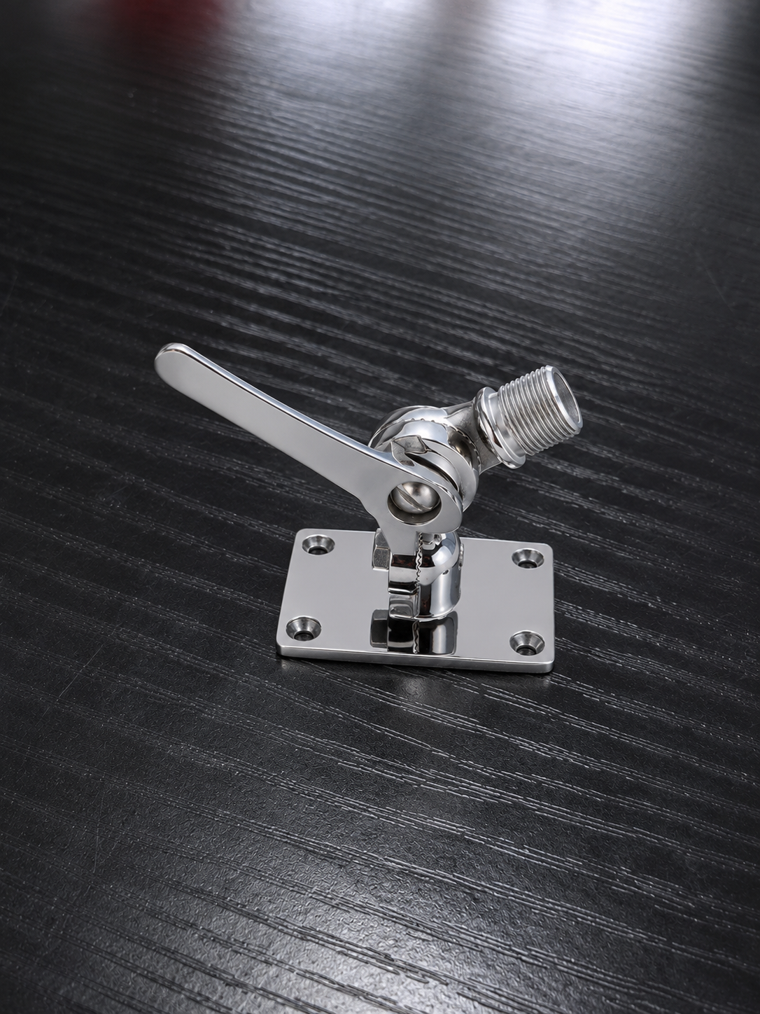
Outdoor antenna mount drainage became a concern after several rotation bases accumulated water during field use. The machined components had passed dimensional inspection, and the drain holes were open before assembly.
After repeated rainfall, however, water remained inside the lower cavity. Corrosion marks appeared near fasteners, and the rotational movement became less consistent.
The problem was not a missing drain hole. It was the location of the hole relative to the installed position.
The Drawing Position Was Not the Field Position
During machining inspection, the rotation base was placed flat on a table. In this orientation, the drain hole appeared close to the bottom of the cavity.
The antenna was installed on a pole with a slight angle. Once assembled, the actual lowest point shifted away from the hole.
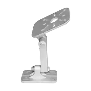
A raised internal rib also separated the cavity into two areas. Water could enter one side but could not reach the existing outlet.
The original drawing had considered the component coordinate system without fully considering its final mounting orientation.
Tracing the Water Path
A controlled water test was performed using the complete assembled mount.
Colored water showed that rain entered through normal assembly gaps and collected behind the internal rib. Surface tension allowed a shallow layer to remain even after the mount stopped moving.
The drain hole was technically lower than several surrounding features, but it was not located at the true collection point. Its small entry chamfer also left a slight edge that retained water.
Relocating the Drain Hole
The installation angle and complete rotation range were reviewed in the assembly model.
The drain hole was moved to the lowest point under the specified mounting condition. A second outlet was added where the base could be installed in more than one orientation.
Internal surfaces were given a slight slope toward the outlets. Local pockets and interrupted passages were removed where they did not serve a structural function.
The hole diameter was selected to discharge water while limiting entry by insects and debris. A protective screen or external cover could be used when required, but it could not restrict the flow path.
Controlling the Machined Features
The drain holes were machined after the main cavity so their positions could be referenced from the functional mounting datums.
Internal intersections were deburred to prevent chips or raised edges from blocking flow. The hole direction also avoided directing discharged water toward cables, bearings, or electrical connectors.
Surface treatment coverage was checked inside the drain holes because exposed aluminum could become the starting point for corrosion.
Verifying the Revised Design
The modified mount was tested at the minimum and maximum permitted installation angles. Water was introduced from several directions while the rotation base moved through its operating range.
After the test, the mount was inspected for standing water in the main cavity, behind ribs, around fasteners, and near the bearing seat.
The revised outlets allowed water to drain without manual tilting. No visible accumulation remained after the specified drainage period.
This outdoor antenna mount drainage case shows that adding a hole is not enough. The true installed angle, internal barriers, surface slope, outlet size, debris protection, and nearby components must be reviewed as one drainage system.
We manufacture CNC antenna mounts, outdoor sensor supports, rotation bases, and weather-exposed aluminum components. Send us your 3D model, installation angle, environmental requirements, and surface treatment for a manufacturability review.