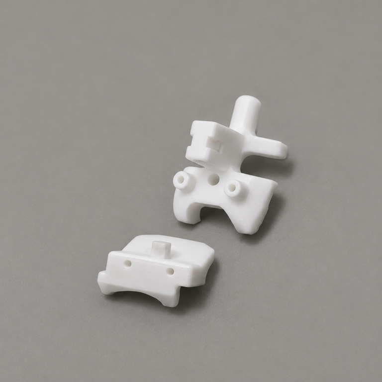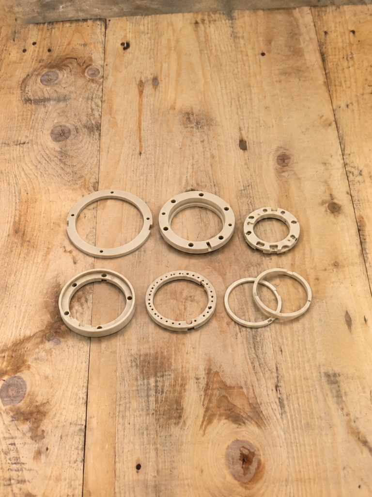
Tablet Press Die Polishing Dimensional Control
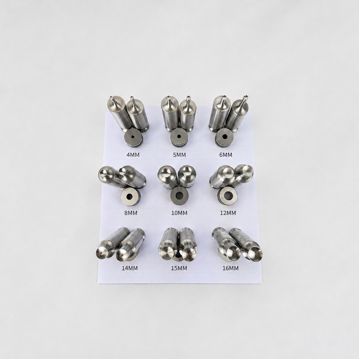
Tablet press die polishing dimensional control became critical after a die cavity passed machining inspection but showed edge-size variation following mirror polishing.
The cavity surface met the required visual finish, yet material removal near the opening changed the edge profile. The final geometry no longer matched the approved drawing even though the polished surface appeared smooth and defect-free.
Finding the Change After Polishing
The cavity dimensions were first inspected immediately after precision machining. Width, depth, profile, and edge location were within tolerance.
After polishing, the cavity opening measured slightly larger in several areas. Optical inspection also showed that the edge transition was no longer uniform. Some sections retained the specified profile, while others had been rounded more heavily.
The change followed the polishing direction and the areas where the operator had applied additional pressure. This indicated controlled material removal rather than machining instability.
Defining Which Surfaces May Change
A general instruction such as “mirror polish” did not provide enough manufacturing control. It described the desired appearance but did not define allowable stock removal or edge geometry.
The drawing was therefore reviewed to separate functional surfaces from cosmetic or non-critical areas. Cavity profile, land width, corner radius, engraving details, and mating surfaces were assigned clear dimensional and surface-finish requirements.
Edges were not assumed to be either perfectly sharp or freely rounded. The required radius or edge break was specified because both conditions affect the final tablet geometry and tooling performance.
Preparing the Surface Before Polishing
The machining process was adjusted to leave a consistent surface with minimal cutter marks. A uniform pre-polish condition reduced the need for aggressive manual correction.
Finishing tools followed the cavity profile with controlled step-over and tool condition. Deep marks, chatter, and local high spots were removed during machining rather than passed to the polishing stage.
Where appropriate, a small and defined polishing allowance was included. The allowance was based on the finishing method and tolerance rather than added as a general amount across every surface.
Protecting the Cavity Edge
The polishing sequence began with the least aggressive abrasive capable of removing the remaining machining texture. Abrasive grade, tool shape, rotational speed, contact pressure, and polishing time were standardized.
Tools were selected to match the cavity geometry. Oversized felt wheels and flexible abrasive points were avoided near critical edges because they could roll over the opening and remove material from both surfaces.
Critical lands and adjacent faces were protected with suitable masking or dedicated polishing fixtures where practical. Tool movement was directed away from sensitive edges instead of repeatedly crossing them.
Operators used magnification and controlled lighting to identify remaining marks without over-polishing areas that had already reached the required finish.
Measuring During the Finishing Process
Inspection was moved into the polishing sequence rather than performed only after completion.
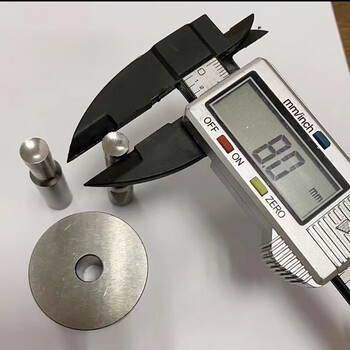
The cavity was cleaned and checked after each defined polishing stage. An optical measurement system evaluated opening size, edge radius, profile, and local blending. Surface finish was verified separately with an approved method suitable for the cavity shape.
Reference samples helped operators distinguish an acceptable mirror finish from unnecessary additional polishing. This reduced variation caused by subjective visual judgment.
Approving the Final Tooling Geometry
Final acceptance included cavity dimensions, depth, profile, edge condition, surface finish, and comparison with the approved model. Measurements were taken only after all polishing residue had been removed.
The corrected process produced the required reflective surface while maintaining the functional cavity geometry.
This tablet press die polishing dimensional control case shows that polishing must be treated as a precision manufacturing operation. Defined edge geometry, a stable pre-polish surface, controlled abrasives, intermediate inspection, and measurable acceptance criteria are necessary to protect tight dimensions.
We manufacture precision tablet tooling, forming dies, punches, mold inserts, and other polished components. Send us your drawing, material, cavity profile, surface-finish requirement, and dimensional tolerances for a manufacturability review.