Saving an Oversized CNC Bore with a Repair Bushing
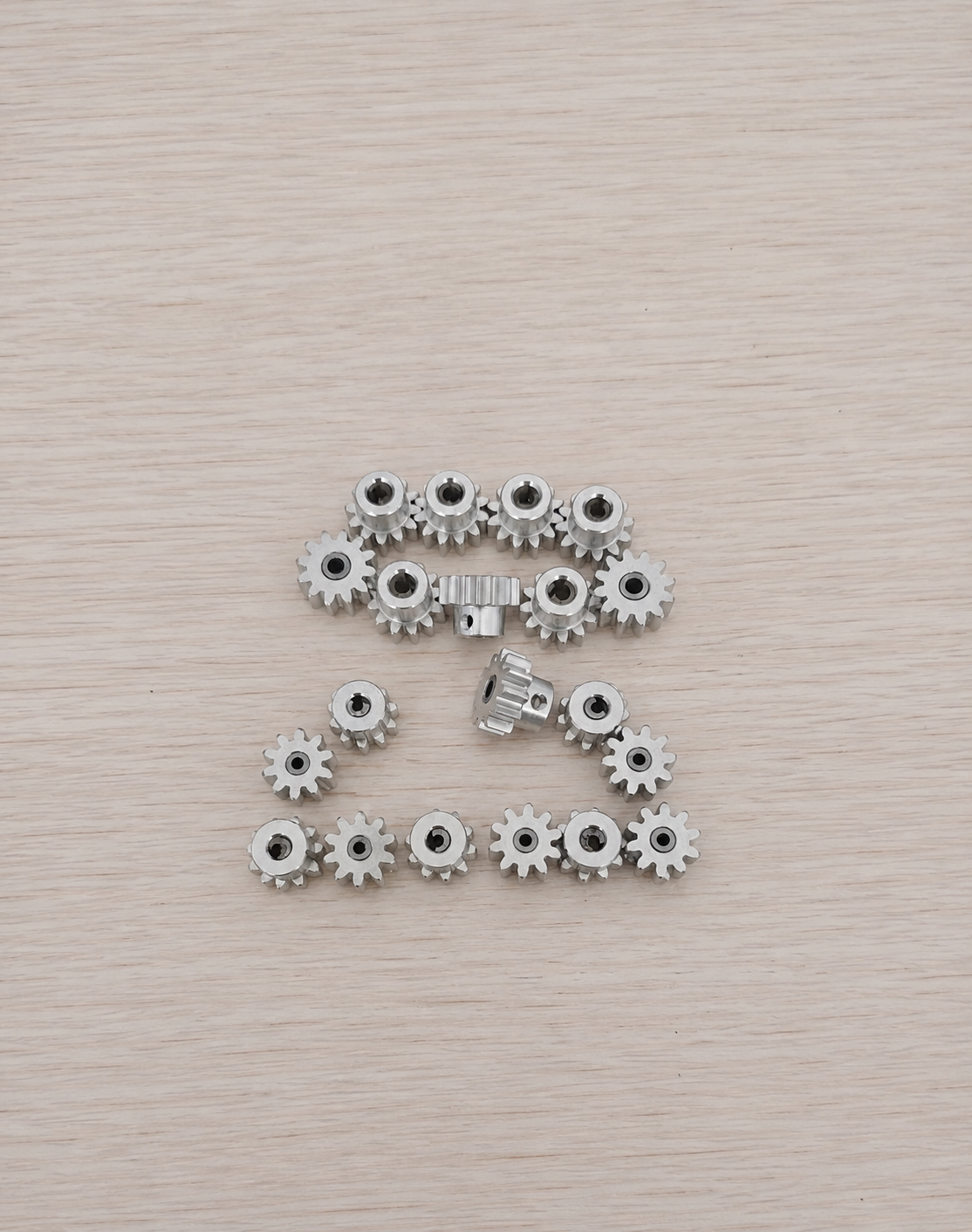
Bore repair with bushing became an option when a high-value machined component failed final inspection. The bore was larger than its upper tolerance limit, but the surrounding geometry remained accurate.
Scrapping the complete part would have wasted substantial material and machining time. Before repair began, the team had to determine whether a bushing could restore the original function without weakening the component.
The repair proceeded only after engineering and customer approval.
Determining Whether the Part Was Repairable
The oversized bore was inspected for diameter, roundness, position, perpendicularity, and surface damage.
A bushing could correct diameter and surface condition, but it could not automatically repair a severely misplaced hole. The original bore axis therefore had to remain close enough to the required position for controlled re-machining.
Wall thickness around the bore was also reviewed. Enlarging the hole to accept a bushing could not reduce the surrounding section below its structural requirement.
Parts exposed to pressure, fatigue, high temperature, or regulated service required additional approval before any repair was accepted.
Designing the Repair Bushing
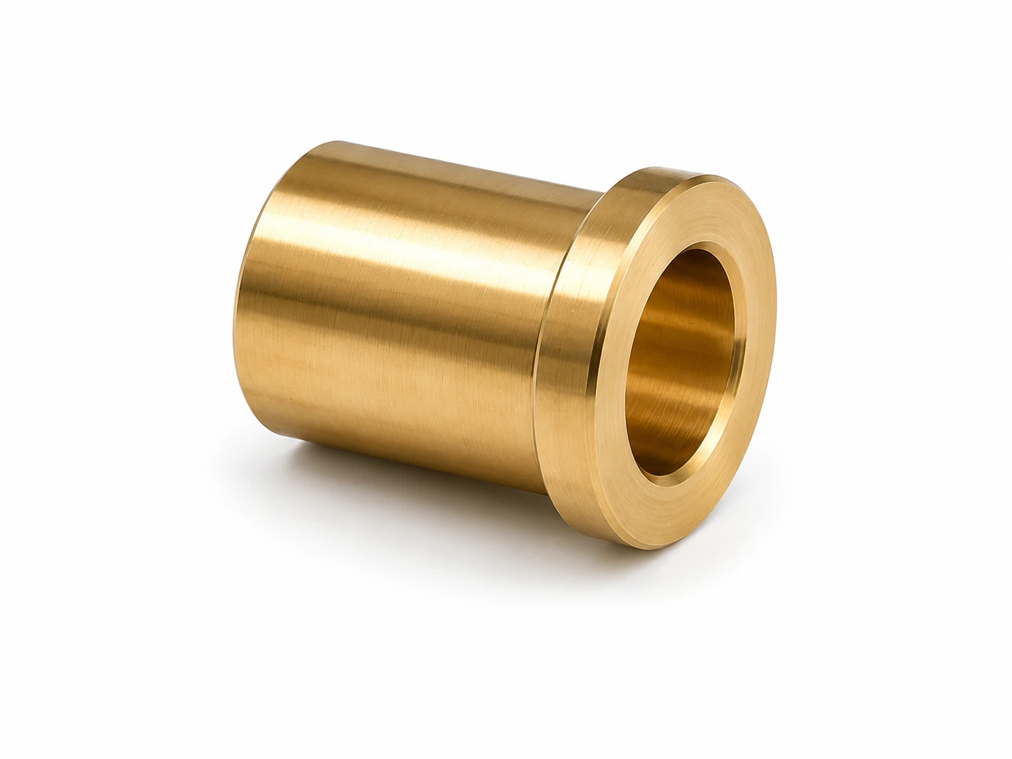
The bushing outside diameter was designed to fit a newly machined repair bore. Its inside diameter included finishing allowance so the final functional bore could be machined after installation.
Material selection considered strength, wear, corrosion, thermal expansion, and compatibility with the parent component.
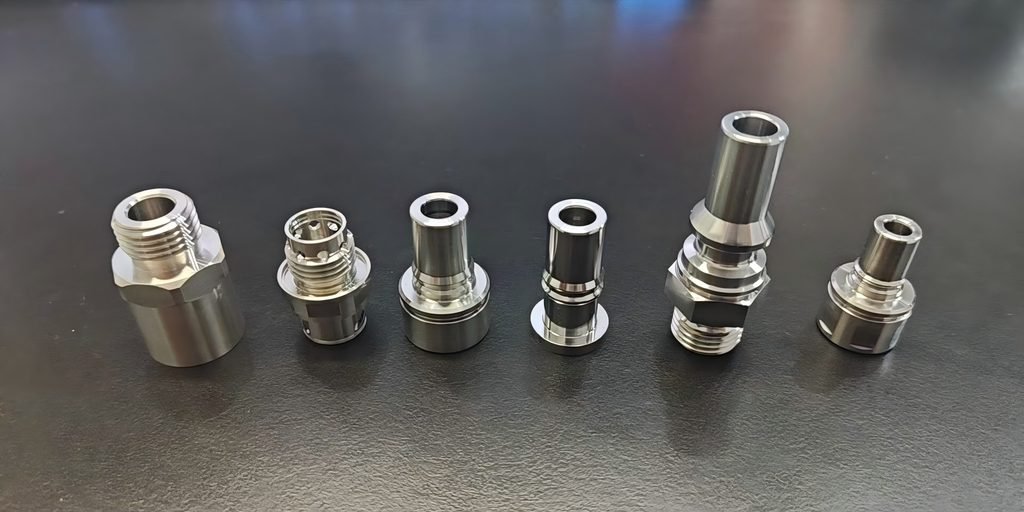
The required interference was based on the bushing diameter, wall thickness, base material, operating temperature, and assembly method. Excessive interference could crack or distort the component, while insufficient retention could allow the insert to move.
A flange, retaining compound, locking feature, or mechanical staking could be added when the application required extra security.
Preparing the Oversized Bore
The defective bore was not used directly for installation. It was enlarged and finish-machined to create a round, straight, and controlled seating diameter.
The repair bore was located from the component’s original functional datums. This allowed the final bushing bore to recover the intended position rather than follow the existing oversized surface.
Entry chamfers were controlled to support installation without reducing the effective contact length.
Installing the Bushing
Both mating surfaces were cleaned before assembly. The bushing was pressed into the component using aligned tooling that applied force evenly.
Where permitted, thermal assembly was used to reduce insertion force. The component could be warmed or the bushing cooled within approved temperature limits.
After installation, the part was allowed to return to inspection temperature before machining continued. The bushing was checked for movement, cracking, incomplete seating, and parent-material distortion.
Finishing the Functional Bore
The installed bushing was bored or reamed to the final size using the original component datums.
Final inspection covered bore diameter, roundness, position, perpendicularity, and the relationship to adjacent features. The external area was also checked for deformation caused by the press fit.
A functional gauge or mating shaft confirmed assembly performance. When required, pull-out, pressure, or load testing verified the bushing’s retention.
The repaired component met the drawing requirements and was released with documented customer approval and inspection records.
This bore repair with bushing case shows that a dimensional defect does not always require scrapping the complete part. A successful repair depends on engineering authorization, sufficient wall thickness, controlled interference, datum-based re-machining, and complete final verification.
We manufacture precision components and evaluate approved repair options for oversized bores and damaged bearing seats. Send us your drawing, inspection report, material, operating conditions, and acceptance requirements for a repair assessment.